Searched the forum but didn't find much help. Link me if something is relevant.
Probing the collective minds here for suggestions.
During pre-flight, 19 times out of 20 I check the electric trim's operation.
It always worked.
Last Sunday was one of those, "naw, it worked perfectly last time" skip the trim check moment...
On initial climb, as I had to hold back pressure to keep +/- 100KIAS, I activated the stick's hat-switch for nose up. No Joy.
Levelled off, speed increased, only slight back pressure needed but still no response from the hat-switch.
Tried the rear stick hat-switch, nothing...
Turned the A/P on to see if that could command the trim but no... Message to "Trim Nose UP" of course.
Function of A/P buttons on the SV-AP-PANEL are OK.
Checked the VP-X breaker to the SV-AP-PANEL, was OK, reset anyway (OFF/ON) but no change.
No issues handling the RV, slowed to approach speed, flaps down, flared and landed quite normally, just some extra back pressure needed on the stick. Easily manageable.
Shut down completly, waited a few moments for any magic to happen and restarted all as usual. Still no trim.
Previous flight was with a passenger (RV-8), this one was solo, explaining the more nose down trim on approach, requiring extra back pressure.
Since new, (Nov. 2021, 125 hours) trim operated normally, never an intermittent episode.
Since that last flight, all attemps to operate the trim were negative.
Setup:
Dynon HDX.
SV-AP-PANEL wired for auto-trim. (serial # 6474, not concerned by SB-00090).
VP-X providing power to SV-AP-PANEL.
Ray Allen T3-12A trim servo (2011 - 2012 ish).
Front and rear Infinity Aerospace grip sticks with hat-switches.
Here's a summary of what was checked this past week.
Dynon network check shows all modules "Ready", no fault messages.
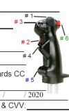
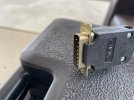
Disconnected the 15 pin connector from the SV-AP-PANEL, (wired as per Dynon's instructions).
Measured 13.1 Volts between pins #9(+) and #2 GND.
Applied power from a battery to motor pins #7 & #8 and servo motor responds both ways.
Checked electrical continuity in wires from pins #3, #4, #5, and #6 to their respective ends in both hat-switches.
Checked above 4 wires that they are not grounded except when hat-switches are operated.
Hat switches grounds were checked OK.
To me, all wiring seem sound, tell me if I missed something.
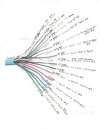
Further, with the system powered and no trim command input, this is what I measured (Volts) on each of the 5 wires running back to the servo:
Between WHT/ORG and any of the 2 (motor) WHT: 4.95
Between WHT/ORG and WHT/BLU (ref): 4.95
Between WHT/ORG and WHT/GRN: (pos) 2.68
Can anyone say if these are desireable values or can anyone measure their values if your similar system is under maintenance or construction??
I will also post this on VAF for support on these findings.
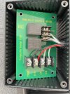
With all this, I'm starting to suspect the SV-AP-PANEL's internal trim circuit board or 15 pin connector.
I would try another module if there was one available for swap on or near my field. Still looking...
Thank you for reading !!
Probing the collective minds here for suggestions.
During pre-flight, 19 times out of 20 I check the electric trim's operation.
It always worked.
Last Sunday was one of those, "naw, it worked perfectly last time" skip the trim check moment...
On initial climb, as I had to hold back pressure to keep +/- 100KIAS, I activated the stick's hat-switch for nose up. No Joy.
Levelled off, speed increased, only slight back pressure needed but still no response from the hat-switch.
Tried the rear stick hat-switch, nothing...
Turned the A/P on to see if that could command the trim but no... Message to "Trim Nose UP" of course.
Function of A/P buttons on the SV-AP-PANEL are OK.
Checked the VP-X breaker to the SV-AP-PANEL, was OK, reset anyway (OFF/ON) but no change.
No issues handling the RV, slowed to approach speed, flaps down, flared and landed quite normally, just some extra back pressure needed on the stick. Easily manageable.
Shut down completly, waited a few moments for any magic to happen and restarted all as usual. Still no trim.
Previous flight was with a passenger (RV-8), this one was solo, explaining the more nose down trim on approach, requiring extra back pressure.
Since new, (Nov. 2021, 125 hours) trim operated normally, never an intermittent episode.
Since that last flight, all attemps to operate the trim were negative.
Setup:
Dynon HDX.
SV-AP-PANEL wired for auto-trim. (serial # 6474, not concerned by SB-00090).
VP-X providing power to SV-AP-PANEL.
Ray Allen T3-12A trim servo (2011 - 2012 ish).
Front and rear Infinity Aerospace grip sticks with hat-switches.
Here's a summary of what was checked this past week.
Dynon network check shows all modules "Ready", no fault messages.
Disconnected the 15 pin connector from the SV-AP-PANEL, (wired as per Dynon's instructions).
Measured 13.1 Volts between pins #9(+) and #2 GND.
Applied power from a battery to motor pins #7 & #8 and servo motor responds both ways.
Checked electrical continuity in wires from pins #3, #4, #5, and #6 to their respective ends in both hat-switches.
Checked above 4 wires that they are not grounded except when hat-switches are operated.
Hat switches grounds were checked OK.
To me, all wiring seem sound, tell me if I missed something.
Further, with the system powered and no trim command input, this is what I measured (Volts) on each of the 5 wires running back to the servo:
Between WHT/ORG and any of the 2 (motor) WHT: 4.95
Between WHT/ORG and WHT/BLU (ref): 4.95
Between WHT/ORG and WHT/GRN: (pos) 2.68
Can anyone say if these are desireable values or can anyone measure their values if your similar system is under maintenance or construction??
I will also post this on VAF for support on these findings.
With all this, I'm starting to suspect the SV-AP-PANEL's internal trim circuit board or 15 pin connector.
I would try another module if there was one available for swap on or near my field. Still looking...
Thank you for reading !!
Last edited: