ALT/Amps not showing anything

d3mac123

Member
Joined
Oct 6, 2020
Messages
94
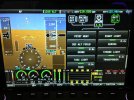
I have the shunt connected to the EMS and configured (I assume properly) in the Skyview. However (I know this picture was taken on the ground but I have the same results while flying with the ALT on), I just get this "Crossed" widget nothing showing any info about the amps.

Any ideas on how to setup it up properly in the Skyview and/or Advanced Control Module?
 

Attachments

  • IMG_4360.JPG
    IMG_4360.JPG
    3.1 MB · Views: 141

rjones560

Member
Joined
Dec 13, 2019
Messages
110
Location
Las Vegas
Is the shunt wired as a load meter (load from alternator goes through it) or is it wired between the battery and the and the main bus so it tells you amps in and out of the battery?
 

d3mac123

Member
Joined
Oct 6, 2020
Messages
94
The shunt is wired to the alternator (it is a Velocity, with the battery far away in the front, while the shunt is close to the engine in the back).
 

RVDan

I love flying!
Joined
Aug 8, 2012
Messages
281
Location
Frederick, MD
For a loadmeter indication (alternator output in amps) the main connections (big terminals) of the shunt should be in series with the alternator output wire. The 2 small terminals should be through fuses near the shunt and then go to the EMS. If either fuse is open, the amps will indicate off scale as the input to the EMS is a 50 mV full scale. The amps measurement is a differential voltage input. An open will result in a 14v differential.
 

rjones560

Member
Joined
Dec 13, 2019
Messages
110
Location
Las Vegas
I have the shunt connected to the EMS and configured (I assume properly) in the Skyview. However (I know this picture was taken on the ground but I have the same results while flying with the ALT on), I just get this "Crossed" widget nothing showing any info about the amps.

Any ideas on how to setup it up properly in the Skyview and/or Advanced Control Module?
Go to the
For a loadmeter indication (alternator output in amps) the main connections (big terminals) of the shunt should be in series with the alternator output wire. The 2 small terminals should be through fuses near the shunt and then go to the EMS. If either fuse is open, the amps will indicate off scale as the input to the EMS is a 50 mV full scale. The amps measurement is a differential voltage input. An open will result in a 14v differential.
RVDAN explained exactly how things work when wired as a load meter. However if you have an open circuit on one of the voltmeters I am uncertain what you will see. It would depend on the software engineers choices since what comes out the other end is digital instead of analog. What RVDAN says is exactly right in an analog world. What happens after the analog data hit the EMS module depends on software choices. You might ask the Dynon tech support people about what you are seeing. It might be consistent with an open circuit on one of the voltmeter leads.
 

rjones560

Member
Joined
Dec 13, 2019
Messages
110
Location
Las Vegas
Instead of fuses I used 26 gauge wire, per the install manual.
I don’t really like that choice much because you are using the 26 gauge wire as a fuse. If there is a short I would rather find the short and replace the fuse that replace the wire. How many inches of 26 gauge wire did you use? Is it attached directly to the shunt, with larger wire after that? I would point out that the voltmeter leads are hooked directly to the main line coming from the alternator. In the case of a short there would be 60 amps available to burn wiring up, which is why I used fuses right next to the shunt. However the 26 gauge wire will work fine if it is fairly short and the short length right next to the shunt. I would check for continuity on the wire from the shunt voltmeter leads to the EMS. I am guessing you loaded the 4 cylinder Continental or Lycoming defaults for the EMS so the proper terminals should be configured for the shunt. However that can be checked by looking at what the pins for the volt meters were configured for in the EMS software.
I am guessing that this is a new install that has never worked correctly. If it was working once I would look at things differently.
 

jnmeade

Active Member
Joined
Oct 9, 2011
Messages
321
Location
Eastern Iowa
You should perhaps address your objection on 26 AWG wire to Dynon.
"There are two methods for accomplishing this. You may simply connect two 1 amp fuses in-line between the shunt and the SV-EMS-220. Or, you may use butt splices to connect 1” to 2” (25mm to 50mm) sections of 26 AWG wire between the shunt and each of the Amps leads connecting to the SV-EMS-220. These fusible links are a simple and cost-effective way to protect against short-circuits (fusible links in LSA installations may not be ASTM-compliant)."
See also Fig 90 Install manual Revision AL. page 7-65.
 

rjones560

Member
Joined
Dec 13, 2019
Messages
110
Location
Las Vegas
You should perhaps address your objection on 26 AWG wire to Dynon.
"There are two methods for accomplishing this. You may simply connect two 1 amp fuses in-line between the shunt and the SV-EMS-220. Or, you may use butt splices to connect 1” to 2” (25mm to 50mm) sections of 26 AWG wire between the shunt and each of the Amps leads connecting to the SV-EMS-220. These fusible links are a simple and cost-effective way to protect against short-circuits (fusible links in LSA installations may not be ASTM-compliant)."
See also Fig 90 Install manual Revision AL. page 7-65.
There is nothing wrong with using the short 26 gauge wire as fuseable links if they are close to the shunt. I don’t like that method from a maintenance point of view but from a safety point of view that will work as the 26 gauge wire will burn through quickly in the case of a direct short.
 

david2wilcox

I love flying!
Joined
Jun 22, 2017
Messages
5
Location
Payson AZ KPAN
I have the shunt connected to the EMS and configured (I assume properly) in the Skyview. However (I know this picture was taken on the ground but I have the same results while flying with the ALT on), I just get this "Crossed" widget nothing showing any info about the amps.

Any ideas on how to setup it up properly in the Skyview and/or Advanced Control Module?
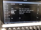
Regardless of how the shunt is installed per Installation manual (chapter 7, SV-EMS-220/221 Installation and Configuration, page 7-64, figure 77), there should not be a red X displayed. Check the EMS Mapping, Sensor Input Mapping screen. Pins 24 and 25 should be programed with Function AMPS, Sensor AMMETER SHUNT (100412-000), Name per your installation (mine is ALT). I have the shunt installed in the alternator leg, so that is how the layout is labeled.
 

Attachments

  • 57B104BC-11C9-414B-B2F5-E2E5B81FF11D.jpeg
    57B104BC-11C9-414B-B2F5-E2E5B81FF11D.jpeg
    2.6 MB · Views: 134

rjones560

Member
Joined
Dec 13, 2019
Messages
110
Location
Las Vegas
This is most puzzling. With what I see in the screen shot and your description of the wiring it should work fine. Pin 24 should be wired to the alternator side of the shunt and 25 to the opposite side. I am guessing that you already verified that. The only other thing that comes to mind is if there is continuity between the shunt and pins 24 and 25. If there is then I would start wondering if there was an internal problem with the EMS. That does not seem likely, but it is possible.
 

david2wilcox

I love flying!
Joined
Jun 22, 2017
Messages
5
Location
Payson AZ KPAN
R Jones. The screen is not from the fellow having the problem (d3mac123). I agree that a continuity check from the shunt to the EMS pins 24 and 25 is appropriate.
 

rjones560

Member
Joined
Dec 13, 2019
Messages
110
Location
Las Vegas
Thanks for pointing that out. I lost track of who was posting. I just got rotator cuff surgery a few days ago so I am probably not that attentive. I am thinking that if the voltage leads were hooked up backwards it should still work. You would just get minus amps instead of plus amps. However since a digital signal leaves the EMS I can’t be sure about software choices. I always get positive amps because mine is wired as a load meter from both alternators. Do any of you have it wired between the main buss and the battery. How does it behave.
 
Top