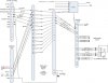
I would appreciate the groups wisdom on the puzzle because I would like to get it right the first time. I am sure someone here has connected the Dynon Com to a PS engineering audio panel...
I am connecting Dynons Com radio to a PS engineering PMA5000EX, and I am not really understanding pin 2 on the Dynon Com, Microphone/PTT ground, and how to handle the grounds in this combination.
This is probaby mostly a case of the two companies using different labeling protocalls and that confusing me, but Dynon's manual is completely geared to matching the Com-425 to their intercom and gives little information about connecting the COM-425 to other audio panels.
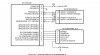
Pins of note:
Dynon Pin 10 Phones Out
Dynon Pin 9 Phones Ground
Dynon Pin 5 PTT IN
Dynon Pin 1 MIcrophone IN
Dynon Pin 2 MIcrophone PTT Ground
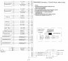
PMA 5000EX Pin 9 Com1 Audio HI
PMA 5000EX Pin 10 Com1 Audio LO
PMA 5000EX Pin 11 Com1 Mic Audio HI
PMA 5000EX Pin 12 Com1 Mic Key
The Shields on this connector of the PMA all ground with the chassis. The PMA manual also states "All shields ground at audio panel only"
Thanks for the help, Doug
I am connecting Dynons Com radio to a PS engineering PMA5000EX, and I am not really understanding pin 2 on the Dynon Com, Microphone/PTT ground, and how to handle the grounds in this combination.
This is probaby mostly a case of the two companies using different labeling protocalls and that confusing me, but Dynon's manual is completely geared to matching the Com-425 to their intercom and gives little information about connecting the COM-425 to other audio panels.
Pins of note:
Dynon Pin 10 Phones Out
Dynon Pin 9 Phones Ground
Dynon Pin 5 PTT IN
Dynon Pin 1 MIcrophone IN
Dynon Pin 2 MIcrophone PTT Ground
PMA 5000EX Pin 9 Com1 Audio HI
PMA 5000EX Pin 10 Com1 Audio LO
PMA 5000EX Pin 11 Com1 Mic Audio HI
PMA 5000EX Pin 12 Com1 Mic Key
The Shields on this connector of the PMA all ground with the chassis. The PMA manual also states "All shields ground at audio panel only"
Thanks for the help, Doug