SV-HARNESS-INT question

JurgenRoeland

New Member
Joined
Oct 12, 2023
Messages
15
Hi all, I am planning on buying the SV-HARNESS-INT harnass for the intercom as it seems too many wires to handle conveniently by myself.

The manual of the intercom states about ground loops and shield grounding :
Because other electrical loads can cause large current flows in a ground path, audio system grounds should be isolated as much as possible from electrical ground. Except where specifically directed in the wiring diagrams above, the shields for all audio cables should terminate at a single point, with that point connected directly to the SV-INTERCOM-2S's MASTER GROUND (Pin 1). Additionally, the point should be as close to the SV-INTERCOM-2S side of your harness as possible

can I assume when I buy the harness that this joining of shield grounds to one point and then to pin 1 is already handled inside the pre-made harnass ?
or should I still open the connector of the harnass and do some kind of magic to bring it all together ?
as it says "as close to the intercom as possible" I assume that this is part of the harness but just want to make sure
 

Rhino

Well-Known Member
Joined
Jul 20, 2009
Messages
1,443
It does not come that way because different builders add different equipment, and choose their own grounding methodology.
 

JurgenRoeland

New Member
Joined
Oct 12, 2023
Messages
15
does someone have an example that shows how you do that (bringing all these shields together ? the manual says to wind all cables together. That seems like a lot of cables to go to one single pin point. How do you manage that in or so close to the connector of the intercom. If someone could share an image as an example of his implementation that would be very helpfull. thanks in advance
 
Last edited:

rjones560

Member
Joined
Dec 13, 2019
Messages
100
Location
Las Vegas
Ground loops are caused by the ground current taking more than one path. The best thing to do is not use airframe ground for anything. I ran all my grounds for everything back to a single point.
 

rjones560

Member
Joined
Dec 13, 2019
Messages
100
Location
Las Vegas
The shields are rather large. You can solder a short lead on to them and fold them back over the shielded wire and shrink rude them in place. Now you just have the smaller single wire to ground. You can crimp a terminal end on them and ground them on a single screw, or with avionics there are usually several several grounding terminals on the backing plate that holds the connectors.
 

JurgenRoeland

New Member
Joined
Oct 12, 2023
Messages
15
I understood indeed the part of a solder sleeve and a single wire pigtail as a connection point to facilitate. what I can't physically picture yet is the point in the manual where it says to wind the 6 or even 9 wires together in a single joint to join pin 1 of the intercom. the point where you join on the gnd pin 1 wire, is that somewhere away from the connector ? (so stripping some insulation in the middle of the wire and bundling all the shield gnd connections there ?) I saw this mentioned in the dynon manual on page 16-16 "Terminating Shielded Cables to Pin 1 of SV-INTERCOM-2S". it's just hard to picture up to 9 connections together on a single 20awg wire.
 

ge

Member
Joined
Sep 16, 2008
Messages
35
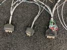
This worked for me. The green wires are pigtails to the shields.
 

Attachments

  • IMG_2919.jpeg
    IMG_2919.jpeg
    5.3 MB · Views: 79

Rhino

Well-Known Member
Joined
Jul 20, 2009
Messages
1,443
You can simply solder the braids together close to the connector, along with a jumper wire to pin 1. Then just shrink wrap and secure the bundle. No terminal lug is necessary, because pin 1 is electrically equivalent to chassis ground. Just be aware, if you anticipate future revisions to the install, you may have to disassemble that soldered bundle of sheathing, or solder new stuff to it, unless you buy or refabricate another harness.
 

JurgenRoeland

New Member
Joined
Oct 12, 2023
Messages
15
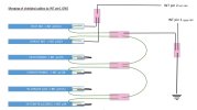
Thanks a lot for all the answers, this together lead me to a solution which leads to how I will wire it as in the image below. hope my findings also help other less experienced builders (like myself) with the same question.

open for comments if something looks wrong

** deleted original picture ***
 
Last edited:

Rhino

Well-Known Member
Joined
Jul 20, 2009
Messages
1,443
That diagram is incorrect. The only thing going to pin 2 should be Pilot Mic Ground and Copilot Mic Ground. Copilot Phones Ground ties in to pin 1 with everything else.
 

JurgenRoeland

New Member
Joined
Oct 12, 2023
Messages
15
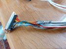
I purchased the intercom harnass and will reply my own initial question. In order to find out more on the internals of the wiring I opened up the shrink tube at the intercom connector and looked what was found underneath.

In short: the purchased harnass comes with the ground wires and shields connected on the main GND wire. See image below. So there is no need to open the main connector nor do any modifications yourself unless you want to remove unused wiring.
I was able to get the shrink tubing on again and will leave it as is.

I hope this helps others with their purchase.
 

Attachments

  • 20240119_131945.jpg
    20240119_131945.jpg
    376.4 KB · Views: 68

Rhino

Well-Known Member
Joined
Jul 20, 2009
Messages
1,443
Great. Most folks add other stuff though, so they'd need to open it.
 
Top