Unstable Reading from "Resistive" (not Capacitive) Fuel Sensor in Right Tank – Calibration Issue

ChrigelsRV8

New Member
Joined
Feb 19, 2025
Messages
8
Location
Basel, Switzerland
Dear Forum,

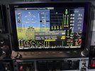
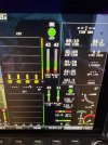
I have been experiencing a persistent issue with the capacitive fuel measurement in the right tank, which has been showing a "full" status for some time. The value does not change, even during flight.

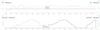
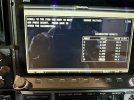
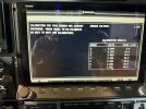
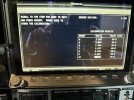
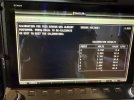
A couple days ago, I performed a recalibration via the SkyView HDX in the EMS. During the process, I noticed that the readings after adding 10 liters of Avgas were unstable. The values fluctuated up and down significantly for several minutes. After approximately 10 minutes, the reading started to stabilize, but it remained inconsistent and not fully reliable.

For comparison, I also recalibrated the left tank, which showed perfectly stable behavior throughout the process.

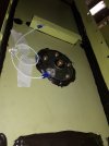
I have installed the 51105 AF-Capacitance Fuel Adapters supplied by Advanced Flight Systems.

Attached you will find some pictures and videos that document the issue.

Does anyone know what might be causing this behavior, and whether there are any known issues or recommended troubleshooting steps?

Thank you in advance for your support.

Kind regards,
Christian Schaerer
Basel, Switzerland


Attachments

  • Right Tank 40-90.jpg
    Right Tank 40-90.jpg
    348.8 KB · Views: 72
  • Right Tank 0-60.jpg
    Right Tank 0-60.jpg
    365.7 KB · Views: 72
  • Left Tank 40-81.jpg
    Left Tank 40-81.jpg
    381.6 KB · Views: 74
  • Left Tank 0-60.jpg
    Left Tank 0-60.jpg
    389.4 KB · Views: 71
Last edited:

CanardMulti

Active Member
Joined
Apr 1, 2021
Messages
131
I have Princeton capacitive senders in my plane. Several years ago, after I did some upgrades that required among other things working deep in tight quarters in the aft portion of the plane, one of my fuel tanks began to constantly read full as well. After extensive trouble shooting I discovered I had inadvertently broken a ground wire - not good anytime but especially a problem in a composite airplane. Once I repaired the ground wire the gauge then read correctly. Whether or not your brand senders work the same way I cannot say, but carefully inspecting ALL the wiring from sender to EMS sure couldn't hurt.
 

ChrigelsRV8

New Member
Joined
Feb 19, 2025
Messages
8
Location
Basel, Switzerland
Thank you for your reply. I think if the ground (or any) wire is broken, then the value would be offset or constantly read full. but the fluctuations are strange. They move up to +-0.6Volts. I ordered a ne capacitive sender. Today I will swap the capacitive senders and see what I get.
 

ChrigelsRV8

New Member
Joined
Feb 19, 2025
Messages
8
Location
Basel, Switzerland
I have to correct my statements above. This was all about the RESISTIVE FUEL SENSOR not the capacitive. I completely messed up the information. I bought and changed to a new capacitive adapter and checked the wiring. Same readings.
Then I realised that it set up my system as follows:
Pin 20: Left restistance (Float type) fuel sensor
Pin 21: Right restistance (Float type) fuel sensor
Pin 22: Left capacitive sensor
Pin 23: Right capacitive sensor

So, the Pin 21 is fluctuating.

Today I added 20 Liters of avgas and filmed the sensor debug page. The plane was steady and the Pin 23 (same right tank) was not moving.
But the Pin 21 went up and down...why is that?
 

swatson999

Well-Known Member
Joined
Oct 6, 2010
Messages
1,668
Just to repeat what's already been said...check the ground wire. Noisy/erratic data is almost always due to bad ground.
 

jakej

Well-Known Member
Joined
Oct 10, 2007
Messages
2,215
Location
Adelaide, Australia
For EMS sensors it’s always better to use a ground from the Dynon EMS unit, you can pair them up if you don’t have any spare ones.😉
ps - I notice the MAP data is also fluctuating - what’s going on there ? Maybe you have other wiring issues too ?
 

airguy

Well-Known Member
Joined
Nov 10, 2008
Messages
1,155
Location
Gods Country - west Texas
Were you on ground power during the calibration or battery power alone? Ground power, like a battery charger, will pulse voltage on/off into the battery on some models, resulting in a higher or lower system voltage over a cycle period of many seconds - this will change the amount of current flowing through a resistive sender, and that changes the voltage drop across that sender, which is what the panel is reading.
 

ChrigelsRV8

New Member
Joined
Feb 19, 2025
Messages
8
Location
Basel, Switzerland
Were you on ground power during the calibration or battery power alone? Ground power, like a battery charger, will pulse voltage on/off into the battery on some models, resulting in a higher or lower system voltage over a cycle period of many seconds - this will change the amount of current flowing through a resistive sender, and that changes the voltage drop across that sender, which is what the panel is reading.
I was only on the battery power.
 

ChrigelsRV8

New Member
Joined
Feb 19, 2025
Messages
8
Location
Basel, Switzerland
For EMS sensors it’s always better to use a ground from the Dynon EMS unit, you can pair them up if you don’t have any spare ones.😉
ps - I notice the MAP data is also fluctuating - what’s going on there ? Maybe you have other wiring issues too ?
I connected the fuel senders ground to the spar with a seperate wire.
 

Attachments

  • 20170427_185018.jpg
    20170427_185018.jpg
    279.1 KB · Views: 12

ChrigelsRV8

New Member
Joined
Feb 19, 2025
Messages
8
Location
Basel, Switzerland
Since I dont want to remove the tank, I will add a ground wire from the spars other side where the bracket with the fuel sender ground cable is attached and connect to a EMS ground wire whick is in this area. This might solve the issue.

Thanks for all the replies.
 

ChrigelsRV8

New Member
Joined
Feb 19, 2025
Messages
8
Location
Basel, Switzerland
For EMS sensors it’s always better to use a ground from the Dynon EMS unit, you can pair them up if you don’t have any spare ones.😉
ps - I notice the MAP data is also fluctuating - what’s going on there ? Maybe you have other wiring issues too ?
I keep an eye on the MAP. Thanks for pointing that out. I had no issues so far. When I calibrated the tank capacity on the battery power only the last time I had no fluctuations on the MAP on savvy. See pic.
 

Attachments

  • MAP-FUEL.jpg
    MAP-FUEL.jpg
    172.8 KB · Views: 10

jakej

Well-Known Member
Joined
Oct 10, 2007
Messages
2,215
Location
Adelaide, Australia
Ok - back to square 1, bear with me as I'm trying to understand your setup -
Post #9 shows a resistive sensor type in an Vans RV - correct?
Do you have a mix of resistive & capacitive sensors as shown in post #4 ?
If yes, then please explain as a 'standard' RV has only left & Right tanks & post # 4 shows 2 x capacitive & 2 x resistive sensors ?
FWIW - I join onto pin 15 (fuel flow power) in the EMS for capacitive power as I believe it is a regulated 12v power output & figure the stable voltage will give better capacitive fuel level sensor readout. YMMV.
BTW - when doing fuel cals in the Rv's I always thump the top of the wing (above the inboard tank rib) after adding each lot of fuel during the calibration process, it reduces the risk of errors due to 'stickiness' of the float arm. Hope this helps.
 
Last edited:

ChrigelsRV8

New Member
Joined
Feb 19, 2025
Messages
8
Location
Basel, Switzerland
Ok - back to square 1, bear with me as I'm trying to understand your setup -
Post #9 shows a resistive sensor type in an Vans RV - correct?
Do you have a mix of resistive & capacitive sensors as shown in post #4 ?
If yes, then please explain as a 'standard' RV has only left & Right tanks & post # 4 shows 2 x capacitive & 2 x resistive sensors ?
FWIW - I join onto pin 15 (fuel flow power) in the EMS for capacitive power as I believe it is a regulated 12v power output & figure the stable voltage will give better capacitive fuel level sensor readout. YMMV.
BTW - when doing fuel cals in the Rv's I always thump the top of the wing (above the inboard tank rib) after adding each lot of fuel during the calibration process, it reduces the risk of errors due to 'stickiness' of the float arm. Hope this helps.
I thumped on top of the wing yesterday during the calibration. This helped a lot. the indication stabilized after a few second and for the first time the indication of the fuel state is correct. Thanks a lot!
I also checked if I ground the sensor at a different spot, but there was no change. I assume the grounding is ok.
I have the Advanced Flight System ACM installed and this is how they instruct to wire the system:
Pin 20: Left restistance (Float type) fuel sensor
Pin 21: Right restistance (Float type) fuel sensor
Pin 22: Left capacitive sensor (enhanced pin)
Pin 23: Right capacitive sensor (enhanced pin)

Right now, I have as soon as I power up the Dynon a Fuel state which summarizes all "four" tanks. I can accept the previous state or manually select, what I have in the L and R tank.
The screen looks like the two pics.
 

Attachments

  • Dynon Fuel Powerup.jpg
    Dynon Fuel Powerup.jpg
    386.7 KB · Views: 17
  • Dynon Fuel state Cap and Float.jpg
    Dynon Fuel state Cap and Float.jpg
    361.3 KB · Views: 18

jakej

Well-Known Member
Joined
Oct 10, 2007
Messages
2,215
Location
Adelaide, Australia
I thumped on top of the wing yesterday during the calibration. This helped a lot. the indication stabilized after a few second and for the first time the indication of the fuel state is correct. Thanks a lot!
I also checked if I ground the sensor at a different spot, but there was no change. I assume the grounding is ok.
I have the Advanced Flight System ACM installed and this is how they instruct to wire the system:
Pin 20: Left restistance (Float type) fuel sensor
Pin 21: Right restistance (Float type) fuel sensor
Pin 22: Left capacitive sensor (enhanced pin)
Pin 23: Right capacitive sensor (enhanced pin)

Right now, I have as soon as I power up the Dynon a Fuel state which summarizes all "four" tanks. I can accept the previous state or manually select, what I have in the L and R tank.
The screen looks like the two pics.
Fantastic result- seems like it’s all okay now 😃
FWIW I’ve never found grounding an issue for the resistive or capacitance units & seeing your setup I figure you did a great job with the build.
 
Last edited:
Top