Mark P.
Visit my builders log at www.ZenithOwner.com
Wiring the radio and intercom seems to be kicking my butt. Mostly because Dynon does not do a good job explaining things in the install manual.
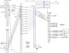
In the pic below, you will see a chart from the install manual. It is page 2-3 for reference.
Question 1: If you look at the red box I've drawn on the photo, I'm wondering what I need to do here. "Radio 1 Audio Input". What is that?? Is it something I need?
I'm only installing one radio so I'm assuming I can ignore anything that says, "Radio 2.
How about "Radio 1 Mic Out" and "Radio PTT"? Do I need those if I'm not installing a separate microphone other than the push to talk button on the stick?
Question 2: Regarding the "Music In" section outlined in green. In the posted photo below, the SV-INTEROM-2S is shown on the left. The Music pins (24, 11, 18) are shown going to a 3.5mm jack. But my intercom already has a 3.5mm music in jack on the on the face of the instrument. So what is this wiring diagram showing? A separate 3.5mm jack perhaps incase I want a second one located somewhere else in the plane?
Question 3: Regarding the Aux muting and non-muting section outlined in blue. Again, what IS this? Is it something I need? What would I install that would connect here? The only thing I can think of is maybe the EFIS-isn't there a voice that comes on and says, "TRAFFIC, TRAFIC"? I'm guessing that would be a non-muting connection? I just have no idea what to wire here or what wire from the EFIS would connect here.
I hope these aren't stupid questions but I've been studying these comm/intercom wiring diagrams and there are some parts of it that I feel should be explained better. Thank you in advance. :-?