Dynon Heated Pitot/AOA Signal Wire

mikemalone

I love flying!
Joined
May 12, 2017
Messages
36
I recently connected the Dynon pitot heater signal wire to my EMS. I think that I was mistaken in my understanding of what information I expected the Skyview display pitot heat widget to give me. I had previously understood that if I switched on the pitot heat, the display would indicate to me that the pitot heater was ON. This hasn’t happened. My thoughts, now, after re-reading the installation manual is that the signal wire’s purpose is, not to let the pilot know that the pitot heat is ON, but to indicate any failure in the pitot heat system. Is my understanding now correct?
 

Rhino

Well-Known Member
Joined
Jul 20, 2009
Messages
1,443
You should get a green indicator with ON, or a red indicator with OFF. Did you use pin 4, 7, 9, 10, 11, 12, 20, or 21, and did you go into the setup menu to map the sensor? (page 15-1).
 

mikemalone

I love flying!
Joined
May 12, 2017
Messages
36
You should get a green indicator with ON, or a red indicator with OFF. Did you use pin 4, 7, 9, 10, 11, 12, 20, or 21, and did you go into the setup menu to map the sensor? (page 15-1).
Yes, pin 10, and I mapped the sensor as per 15-1 of the Installation Manual.
 

Rhino

Well-Known Member
Joined
Jul 20, 2009
Messages
1,443
I don't have one here to play with. Maybe someone else who's familiar with it can chime in. You should get an indication either way.
 

aviatorbob

New Member
Joined
Jan 14, 2021
Messages
4
I followed the instructions in 15-1 (revision AM) and the widget indicates green when the heat is on and working. If you turn the pitot heat off the widget turns red indicating no heat. Should also do that if there is a failure of the heat. Make sure you go thru the full assignment and setup of the widget as indicated in 15-1.
 

tniel7331

New Member
Joined
Mar 24, 2021
Messages
20
I followed the instructions in 15-1 (revision AM) and the widget indicates green when the heat is on and working. If you turn the pitot heat off the widget turns red indicating no heat. Should also do that if there is a failure of the heat. Make sure you go thru the full assignment and setup of the widget as indicated in 15-1.
All its telling you is that there is power on the wire, at wherever you spliced into it. I usually do the load side of the switch. If the tube is actually hot ???? It in no way knows.
 

BobMF8

New Member
Joined
Apr 15, 2022
Messages
10
What ever you do install a resistor in the line that is on the latest revision. The pitot line is usually right to the bus and 15 amps and can momentarily spike ever the EMS system's voltage limit when being turned off and on using old switches that can mess up the EMS and mimic a hardware problem. The version out in late October 22 has resistors for both 24 AND 14 and you can damage the EMS depending on the quality of your legacy wiring, switches, and voltage regulation. I chased this with a borrowed oscope and it ended up that the EMS was electrically damaged on the first switch throw and had to be returned and fixed at Dynon. Resistor wired in and everything was fine after the EMS was reinstalled.
 

mikemalone

I love flying!
Joined
May 12, 2017
Messages
36
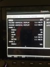
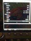
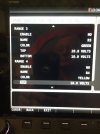
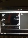
On the widget displayed on the SkyView screen, I have it showing ON and Green continouosly, irrespective of the pitot heat switch position. I configured it as per the pictures attached below. Very confusing.
 

Attachments

  • AD4DDCEA-A085-483C-BC83-8369CD4F9117.jpeg
    AD4DDCEA-A085-483C-BC83-8369CD4F9117.jpeg
    976.9 KB · Views: 103
  • E26201A8-EDBE-448C-89E0-DC271F44FE6F.jpeg
    E26201A8-EDBE-448C-89E0-DC271F44FE6F.jpeg
    872.1 KB · Views: 96
  • 0D97D55E-4790-4B7F-A4F3-DB58BC8AED87.jpeg
    0D97D55E-4790-4B7F-A4F3-DB58BC8AED87.jpeg
    774.6 KB · Views: 103
  • 31961B37-4B11-4512-AD04-0EE466D01D5B.jpeg
    31961B37-4B11-4512-AD04-0EE466D01D5B.jpeg
    773.5 KB · Views: 96

BobMF8

New Member
Joined
Apr 15, 2022
Messages
10
Mike,
Revision D (12-28/22) shows 10k resistors only on 24v systems, Rev. G (10-28/22) shows 10k resistors on EVERYTHING OVER 5v's. That says something. The pitot heat takes more power than most anything on the plane that is connected to the main bus and voltage varies as the temp of the tube heats up. When I installed my system prior to Rev G, I presumed the EMS has some form of voltage protection in it for pickups only to find out it has none. On startup after G first switch push it was done. I didn't know the revision came out and fought it for a week until I figured it out and sent the EMS in.
Go to the diagnostics screen and look at what the EMS thinks the voltage in the line is both off and on. Pop a meter on the pitot line to confirm both off and on. If the meter shows zero off and 12+ on toggling the switch and the diagnostics screen doesn't show a complete zero then you had what happened to me back in January. The EMS isn't sending the right data to the main processor which can only process the data it gets and changing ranges, colors, ect won't fix anything because the voltage changed every time it boots up. Supposedly a general pickup can momentarily handle up to 30 volts. Testing my switches showed it about that that for about a .001/sec and that ruined the EMS and I struggled to diagnose it until I figured out out the EMS failed. Really, it only needs to see 0 to 3 or 4 volts just enough range from the EMS to process the difference as a boolean and a resistor can provide cheap insurance to not voltage slam the circuit using old mechanical switches. The funny part was that I had boxes of 10k resistors just laying around! I have only three lines: gear motor, flap motor, and pitot and all of them have resistors now and everything indicates perfectly on the widgets. Such is the learning curve for old airplanes.
 

Rhino

Well-Known Member
Joined
Jul 20, 2009
Messages
1,443
An inline resistor won't limit current (15 amps was mentioned in post 7). You'd need a drop down resistor for that, which could be used in conjunction with an inline resistor. The EMS inputs don't use anything over 5 volts, and are limited to 15, which is why all the 24 volt systems always called for an inline resistor. But since the EMS inputs don't actually use anything over 5, the resistors were added to the 12 volt systems as well. You can always measure the voltage at the pin to see what you're getting. Just be aware you may see a small voltage even with no input applied. Some of the EMS pins have an internal bias voltage applied.
 

mikemalone

I love flying!
Joined
May 12, 2017
Messages
36
Just to tidy up this thread. After performing a test, at Dynon’s request, using the pin configuration page, it was established that there was a problem with the pitot heater controller. I opted to purchase a new one. Dynon gave me a small reduction in price. Still haven’t flown the aircraft yet, so disappointed that there was a problem at this stage of the build.
 
Top