owenssonex
Member
- Joined
- Jul 22, 2019
- Messages
- 46
(See bottom of this original post for my fix)
Hello,
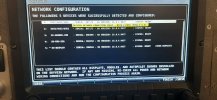
I am assisting the builder of an ELSA RV-12 to diagnose an issue with his roll auto-pilot servo generating " Skyview network connection fault Data 2 pair (Pins 4 & 8) "
-Dynon D1000 screen version 16.0.4.8437 installed
-SV32 servo (serial number 007174, in case that helps with age). Network status indicates the servo has version 16.0.4.8437 also installed
-Auto-pilot is functional 95% of the time on the primary network, I've had a few occasions that the secondary network issue appears to have caused the auto-pilot to disconnect.
-Force network configuration and network detect functions did not clear the issue.
-Continuity test between the SkyView D9 cable, pin 1 to the green wire on the back side of the Molex connector (servo side) indicates 0 (continuity)
-Continuity test between the SkyView D9 cable, pin 6 to the blue wire on the back side of the Molex connector (servo side) indicates 0 (continuity)
-Continuity test between the SkyView D9 cable, pin 4 to the white with blue wire on the back side of the Molex connector (servo side) indicates 68.5. By back side, I mean that the molex connector is fully connected to the servo, the meter probe was in the backside of the connector.
-Continuity test between the SkyView D9 cable, pin 8 to the white with green wire on the back side of the Molex connector (servo side) indicates 74 my cheap meter shows a single 1 on the far left when there is no continuity. 0.0 when there is complete continuity.
-Did not do any continuity testing on the pitch servo, as it is working without issue, and would require the removal of a bunch of seat pan screws.
I disconnected and inspected the molex connections at the servo, they all look good- no corrosion. I very gently squeezed the servo side female connectors to insure good connections, no change.
I verified the molex pinouts on the servo and airframe match the Van's RV-12 plans. (Continuity tests above seem to solidify that the wiring pinouts are good.)
The wiring harness is a native D1000 kit, it does NOT have adapters from a D3.
This testing was with the engine off and only the Dynon components powered on.
The pins on the Vans AV5000 box and the connectors going into the AV5000 both look good. No corrosion, no bent pins, and the thumb screws are tight.
I created a new diagnostic file after completing this latest round of testing. It is 100mb
***FIXED***
Short answer: "Options" port of AV5000 had white with green and white with blue pins reversed. Correct pins are: P3=White with green, P4= White with Blue.
RV-12 AV5000 power box has the Pitch servo in the "Fuselage" connector
P12 Orange brown stripe
P17 Blue pitch servo
P19 Green pitch servo
P29 Red pitch servo power
P32 White with blue stripe pitch servo
P33 White with green stripe pitch servo
P34 and 35 black pitch servo ground
"Options" port has the Roll servo wiring:
P1 Green roll servo
P2 Orange roll servo
P3 White with Green stripe roll servo (FIX, was P4)
P4 White with Blue stripe roll servo (FIX, was P3)
P19 Red pitch servo power
P22 Blue roll servo
To test continuity on the roll servo, the "Fuselage" and "EFIS" ports must also be connected to the AV5000.
Not being the builder and not having access to the plans, I incorrectly feared there was a faulty Y joint at the pitch servo.
If all the ports are connected to the AV5000, you should get continuity between the D1000 D9 connector pin 4 white with blue to the white with blue wire on the servo Molex connector. Partial continuity should point first to reversed pins. The Dynon D9 pin 8 White with Green should have full continuity to the white with green servo wire. Sorry if it is just me, I spent so much time on this that I *INCORRECTLY* started playing head games with how the wire colors probably changed somewhere in the scheme or drifted to a plain white wire.
Thanks,
Jim
Hello,
I am assisting the builder of an ELSA RV-12 to diagnose an issue with his roll auto-pilot servo generating " Skyview network connection fault Data 2 pair (Pins 4 & 8) "
-Dynon D1000 screen version 16.0.4.8437 installed
-SV32 servo (serial number 007174, in case that helps with age). Network status indicates the servo has version 16.0.4.8437 also installed
-Auto-pilot is functional 95% of the time on the primary network, I've had a few occasions that the secondary network issue appears to have caused the auto-pilot to disconnect.
-Force network configuration and network detect functions did not clear the issue.
-Continuity test between the SkyView D9 cable, pin 1 to the green wire on the back side of the Molex connector (servo side) indicates 0 (continuity)
-Continuity test between the SkyView D9 cable, pin 6 to the blue wire on the back side of the Molex connector (servo side) indicates 0 (continuity)
-Continuity test between the SkyView D9 cable, pin 4 to the white with blue wire on the back side of the Molex connector (servo side) indicates 68.5. By back side, I mean that the molex connector is fully connected to the servo, the meter probe was in the backside of the connector.
-Continuity test between the SkyView D9 cable, pin 8 to the white with green wire on the back side of the Molex connector (servo side) indicates 74 my cheap meter shows a single 1 on the far left when there is no continuity. 0.0 when there is complete continuity.
-Did not do any continuity testing on the pitch servo, as it is working without issue, and would require the removal of a bunch of seat pan screws.
I disconnected and inspected the molex connections at the servo, they all look good- no corrosion. I very gently squeezed the servo side female connectors to insure good connections, no change.
I verified the molex pinouts on the servo and airframe match the Van's RV-12 plans. (Continuity tests above seem to solidify that the wiring pinouts are good.)
The wiring harness is a native D1000 kit, it does NOT have adapters from a D3.
This testing was with the engine off and only the Dynon components powered on.
The pins on the Vans AV5000 box and the connectors going into the AV5000 both look good. No corrosion, no bent pins, and the thumb screws are tight.
I created a new diagnostic file after completing this latest round of testing. It is 100mb
***FIXED***
Short answer: "Options" port of AV5000 had white with green and white with blue pins reversed. Correct pins are: P3=White with green, P4= White with Blue.
RV-12 AV5000 power box has the Pitch servo in the "Fuselage" connector
P12 Orange brown stripe
P17 Blue pitch servo
P19 Green pitch servo
P29 Red pitch servo power
P32 White with blue stripe pitch servo
P33 White with green stripe pitch servo
P34 and 35 black pitch servo ground
"Options" port has the Roll servo wiring:
P1 Green roll servo
P2 Orange roll servo
P3 White with Green stripe roll servo (FIX, was P4)
P4 White with Blue stripe roll servo (FIX, was P3)
P19 Red pitch servo power
P22 Blue roll servo
To test continuity on the roll servo, the "Fuselage" and "EFIS" ports must also be connected to the AV5000.
Not being the builder and not having access to the plans, I incorrectly feared there was a faulty Y joint at the pitch servo.
If all the ports are connected to the AV5000, you should get continuity between the D1000 D9 connector pin 4 white with blue to the white with blue wire on the servo Molex connector. Partial continuity should point first to reversed pins. The Dynon D9 pin 8 White with Green should have full continuity to the white with green servo wire. Sorry if it is just me, I spent so much time on this that I *INCORRECTLY* started playing head games with how the wire colors probably changed somewhere in the scheme or drifted to a plain white wire.
Thanks,
Jim
Attachments
Last edited: