Is There an Explanation for Current Readings on HDX whilst its Powered by Backup Battery Only?

Bardample

I love flying!
Joined
Aug 18, 2013
Messages
40
I have just replaced a faulty Dynon EGT probe ( (515 hours since new) on cylinder #1 . I had removed the Earthx ETX 680 battery , as this was faulty as well ( not holding charge after flight, or on the bench after charge out of RV).

When I powered the Dynon HDX with the Dynon backup battery alone, to check that my newly installed EGT probe functioned ( it did) ,I noticed the Ammeter reading was 8Amps and the 'measured output ' from my Monkworkz input was 2.6 Amp. Obvoiusly, the only power supply in the plane at the time was the Dynon supplied back up battery.

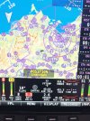
Can anyone explain this to me? See the screen shot of part of my monitor at time.
 

Attachments

  • IMG_5272.jpeg
    IMG_5272.jpeg
    3.4 MB · Views: 53

BlueCrab

New Member
Joined
Jan 6, 2024
Messages
12
From my perspective, explaining this without a schematic, is impossible. I would need to understand how your system is measuring those inputs and any conversions/scaling the Dynon HDX is providing.
 

F18Sailor

New Member
Joined
Mar 20, 2025
Messages
5
Bardample,

Can you share your settings config file for the Monkworkz current, presuming you are using the output from the Monkworkz PCB directly? This is what I have, and my readings are not correct (0A shows as 18A on the display):

sensor={
id=MONKWORKZ CURRENT
function=AMPS
pins=C37_P8 C37_P22 C37_P23 C37_P31
name=MZ30_A
min_val=0
max_val=30
resolution=1
round=.1
is_piecewise=0
low_coeff={
c_x4=0
c_x3=0
c_x2=0
c_x1=6
c_x0=18
}
low_resistance=NONE
low2high_cross=0
high_coeff={
c_x4=0
c_x3=0
c_x2=0
c_x1=0
c_x0=0
}
high_resistance=NONE
high2low_cross=0
shift=5
}
 

Rhino

Well-Known Member
Joined
Jul 20, 2009
Messages
1,806
Are you using the hall effect output from the Monkworkz or a shunt?
Where did you get those polynomial numbers?
If using the proportional current output on pin 5 of the Molex connector, it outputs between 0 to 2.7 volts, corresponding to 0 to 30 amps, so those polynomials seem a bit strange.
 
Last edited:

F18Sailor

New Member
Joined
Mar 20, 2025
Messages
5
I'm using the proportional current output on pin 5 of the Molex connector, and you're correct, those polynomials made little sense. I've since updated them as shown below, but haven't had a chance to test them yet. The other questions I have are:
1) How do you select a low_resistance value? I noticed the other ammeter sensors have a 200 Ohm pullup, so I added that, but I also noted those are likely shunt sensors, not proportional.
2) My contact sensor for the Monkworkz alternator doesn't appear to be working correctly. Configuration below, but it would be helpful if someone with a known-working sensor definition would post their copy!

sensor={
id=MONKWORKZ CURRENT
function=AMPS
pins=C37_P8 C37_P22 C37_P23 C37_P31
name=MZ30_A
min_val=0
max_val=30
resolution=1
round=.1
is_piecewise=0
low_coeff={
c_x4=0
c_x3=0
c_x2=0
c_x1=11.111
c_x0=0
}
low_resistance=PULL_UP_200
low2high_cross=0
high_coeff={
c_x4=0
c_x3=0
c_x2=0
c_x1=0
c_x0=0
}
high_resistance=NONE
high2low_cross=0
shift=5
}

sensor={
id=MONKWORKZ STATUS
function=CONTACT
pins=C37_P4 C37_P6 C37_P7 C37_P8 C37_P9 C37_P10 C37_P11 C37_P12 C37_P20 C37_P21 C37_P22 C37_P23 C37_P31
name=MZ30_S
min_val=0
max_val=5
resolution=1
round=.1
is_piecewise=0
low_coeff={
c_x4=0
c_x3=0
c_x2=0
c_x1=1
c_x0=0
}
low_resistance=PULL_UP_10K
low2high_cross=0
high_coeff={
c_x4=0
c_x3=0
c_x2=0
c_x1=0
c_x0=0
}
high_resistance=NONE
high2low_cross=0
}
 

Kevin D

New Member
Joined
Jul 9, 2019
Messages
20
Well, I have observed similar conditions on my Dual HDX with Dual Dynon Backup Batteries.
Secondary system standby bus backup battery and alternator on a shunt.
Earth X EXP 680.

When non operating, I can see non zero values that I attribute to small differences in ground potential or static charge hanging on an input.
Exploration with VOM and Scope kinda sorta match what is seen on the Dynon Display.
If I start the engine and put the alternator on line, everything lines up and is rock solid.

When engine and charging electrical system are inoperative.
If I disconnect the standby bus backup battery and its associated charging diode things move closer to zero but not all the way.
The Dynon is monitoring both battery voltages but the disconnected standby bus backup battery does not go to zero when disconnected.
If I take the Dynon input to solid ground, Dynon displayed voltage on the standby bus backup battery, it goes to zero.

So battery always is charged, smoke stays in the wires, normal is normal and electronics are still mysterious magic.

Kevin D
 

Rhino

Well-Known Member
Joined
Jul 20, 2009
Messages
1,806
The GP inputs have an internal bias voltage applied, so you'll always see something with a meter if it's powered on. I think he's correct in asking for settings from someone with a working configuration, but I'm curious to see what the results of the latest changes will be when he tests them.
 

Bardample

I love flying!
Joined
Aug 18, 2013
Messages
40
Sorry , I have been absent from here. I am not technically savvy.

I have a shunt on my Alternator Reg output to measure current to battery and aircraft electrics. I have a. Monkworkz generator that feeds parallel into my bus after the shunt( so shunt measured amps do not measure Monkworkz generator output). The Monkworkz current output is measured separately ( as set up on Monkworkz install manual) and reads " Genamps" amp on Dynon EFIS .
I have included in attachment below the settings that Bill from Monkworkz wrote for me to enable the Dynon to give my Monkworkz amp output.

As mentioned in my first post, I was looking for a possible explanation as to why I get to see a small amp read out on both the shunt and Monkworkz amp reads when my master switch ( this is the only power source to to my electrics) is off . Obviously, the Dynon HDX is powered on via the Dynon SV backup battery, when I see readouts that I don't expect. Is the SV battery involved in this with leakage ?

I suspect the amp readouts are due to small potential differences between some connections. As mentioned by a poster above, my readouts for current use whilst in flight seem to be ok and not spurious.

I thankyou for your comments . Jeff
 

Attachments

  • IMG_5504.png
    IMG_5504.png
    377.5 KB · Views: 12

F18Sailor

New Member
Joined
Mar 20, 2025
Messages
5
Next time I'm at the bird I'll try and check what I see on my Dynon Skyview classic (same EMS) with the master bus off. I suspect the small amp readouts are essentially as you suspect, a potential difference between the shunt and the battery ground. This 'bug' is actually a feature in the Oscilloscope world; to accurately measure DC voltages and currents in an electrical system, one needs isolated probes ($$$) or a handheld scope that is internally powered, to avoid tying the DC negative to earth ground.

More details here: https://www.tek.com/en/products/oscilloscopes/oscilloscope-probes/isovu-isolated-voltage-probes

Also, thank you for uploading your Monkworkz configuration file. I found these settings do work on the latest MZ-30L (full range is 0-30A, from 0 to 2.7v, hence setting c_x1 to 11.111)

sensor={
id=MONKWORKZ CURRENT
function=AMPS
pins=C37_P8 C37_P22 C37_P23 C37_P31
name=MZ30_A
min_val=0
max_val=30
resolution=1
round=.1
is_piecewise=0
low_coeff={
c_x4=0
c_x3=0
c_x2=0
c_x1=11.111
c_x0=0
}
low_resistance=NONE
low2high_cross=0
high_coeff={
c_x4=0
c_x3=0
c_x2=0
c_x1=0
c_x0=0
}
high_resistance=NONE
high2low_cross=0
shift=5
}
 

Rhino

Well-Known Member
Joined
Jul 20, 2009
Messages
1,806
This 'bug' is actually a feature in the Oscilloscope world; to accurately measure DC voltages and currents in an electrical system, one needs isolated probes ($$$) or a handheld scope that is internally powered, to avoid tying the DC negative to earth ground.
That brings back memories.

Glad you got the config file sorted out.
 
Top