What are the best practices for tying together multiple power wires to one breaker? I see few instances like the having 2 wires for power on the PFD harness and powering the the com panel and radio where 2 wires would go to one power source. Is it acceptable to crimp two wires in a terminal and are there guidelines to this?
You are using an out of date browser. It may not display this or other websites correctly.
You should upgrade or use an alternative browser.
You should upgrade or use an alternative browser.
Methods for connecting multiple power wires
- Thread starter Ampzapper
- Start date
airguy
Well-Known Member
Keep in mind that the breaker is there to protect the wiring, not the device. If you have multiple power wires originating from a single breaker, you will need to make sure that the breaker will trip if the single smallest wire is shorted to ground - otherwise you are not protected.
Marc_J._Zeitlin
Active Member
This is an excellent point, and is a VERY strong argument for only ever having one component for each CB/fuse, and conversely having one fuse/CB for every component (sometimes it's not possible, but that's pretty rare). And THAT's an argument for fuses, which are a lot cheaper and simpler and more reliable than CBs.Keep in mind that the breaker is there to protect the wiring, not the device. If you have multiple power wires originating from a single breaker, you will need to make sure that the breaker will trip if the single smallest wire is shorted to ground - otherwise you are not protected.
SV_Classic
Active Member
- Joined
- Oct 30, 2024
- Messages
- 103
I'd make the friendly argue that the incremental increase in reliability is too negligible to actually count for anything making CB's as reliable as fuses without the need to have extra fuses stored on-board at all times.
@Ampzapper, the common solution is to use a terminal end that can hold both wires but you do have to be sensitive to the possibility you are either overloading the CB or not sizing the wires correctly. Every wire coming from that CB has to be sized for the CB amp rating. THis is why you sometimes see items where it might be intuitive to put them on one breaker ( a fuel pump and a fuel primer on/off valve for example) but because one is high draw and the other is low draw, they each get their own breaker. The weight savings from not having to wire everything with the heavier wire of the high draw circuit makes the extra CB worth it.
@Ampzapper, the common solution is to use a terminal end that can hold both wires but you do have to be sensitive to the possibility you are either overloading the CB or not sizing the wires correctly. Every wire coming from that CB has to be sized for the CB amp rating. THis is why you sometimes see items where it might be intuitive to put them on one breaker ( a fuel pump and a fuel primer on/off valve for example) but because one is high draw and the other is low draw, they each get their own breaker. The weight savings from not having to wire everything with the heavier wire of the high draw circuit makes the extra CB worth it.
Marc_J._Zeitlin
Active Member
The data might be a bit old, but per MIL Handbook MIL-HDBK-217F (Reliability Prediction of Electronic Equipment), the failure rate of single circuit CBs NOT used as a switch in an airborne, manned environment is approximately 2 * 10e-6, or 2 per every million hours. Fuses, on the other hand, have a failure rate (in the same environment) of approximately 0.1 * 10e-6, or one every 10 million hours. So I'd say that a factor of 20X worse for CBs is not negligible.I'd make the friendly argue that the incremental increase in reliability is too negligible to actually count for anything making CB's as reliable as fuses without the need to have extra fuses stored on-board at all times.
ATO fuses (as used in cars) are tiny, lightweight, easy to remove and install, cheap, and reliable (which are all reasons they're used in cars, rather than CBs). For a more reliable plane, fuses are preferable.
SV_Classic
Active Member
- Joined
- Oct 30, 2024
- Messages
- 103
It seems to me the aviation industry has weighed that data and has universally opted for CB's. Fuses also don't give an immediate indication that they've failed so a simple scan of a fuse panel doesn't provide the insight that a CB panel gives in the pre-flight routine. Looking through the exposed plastic of a tiny fuse to see if the filament has burned through, while an option, isn't practical for an aircraft with many many circuits and would probably breed indifference by pilots, IMHO
Marc_J._Zeitlin
Active Member
I'd strongly suggest that you read "The Aeroelectric Connection", by Bob Nuckolls. Also, having worked in the aerospace industry for the past 20 years, I'm intimately familiar with the "NIH" and "That's the way we've always done things here" attitudes that are prevalent. Except in very few situations, _IF_ an aircraft electrical system for small GA aircraft is architected well, fuses are more reliable (per a System Safety Analysis/FMEA) cheaper, simpler, and safer, than CBs.It seems to me the aviation industry has weighed that data and has universally opted for CB's. Fuses also don't give an immediate indication that they've failed so a simple scan of a fuse panel doesn't provide the insight that a CB panel gives in the pre-flight routine. Looking through the exposed plastic of a tiny fuse to see if the filament has burned through, while an option, isn't practical for an aircraft with many many circuits and would probably breed indifference by pilots, IMHO
The key here is "well architected", which the majority of E-AB aircraft's electrical systems are not.
The argument that "this is what the aviation industry does" would then be an argument for claiming that carburetors and magnetos are somehow safer and more reliable than fuel injection and electronic ignition - claims which are prima facie false. There are better ways - the "aviation industry", at least with respect to GA aircraft, needs to be dragged kicking and screaming into the 21st century (and sometimes, the 20th).
SV_Classic
Active Member
- Joined
- Oct 30, 2024
- Messages
- 103
for a system with a one per million failure rate, the life of a CB in a general aviation aircraft flying forty hours per year is adequately safe. "safer" isn't measurable in a meaningful way at that point. My background is ME and a line pilot for the last 29 years. The safety of a fuse would be greatly offset by the impractical requirement to inspect the status of every single fuse through those tiny cloudy plastic windows before every flight. I'm guessing the reliability of a CB is adequate for commercial aircraft and it's presence ensures they are inspected with the regularity required for safe airline ops._IF_ an aircraft electrical system for small GA aircraft is architected well, fuses are more reliable (per a System Safety Analysis/FMEA) cheaper, simpler, and safer, than CBs.
i get it though, you like fuses, not trying to change your mind, just learning through an interesting discussion
Marc_J._Zeitlin
Active Member
So that's not how SSAs work. The analysis is of the whole SYSTEM. And in GA aircraft, we're generally shooting for a SYSTEM level catastrophic failure rate of less than 1 per 1M hours. So either each component of the system that has a failure rate of < 1/1M hours needs redundant backup, or the failure rate of the component needs to substantially better than 1/1M hours. Having performed the SSA on the WK2, SS2 and RM2 aircraft for Scaled Composites, I'm intimately familiar with how to determine safety levels using aerospace standard procedures and practices.for a system with a one per million failure rate, the life of a CB in a general aviation aircraft flying forty hours per year is adequately safe. "safer" isn't measurable in a meaningful way at that point.
So the electrical SYSTEM needs to catastophically fail < 1/1M hours. If there are 10 CBs in the system which control safety of flight components, and each has an independent failure rate of 2 * 10e-6, that's a total failure rate of 20 * 10e-6 - 20X the allowable failure rate. 10 fuses, however, would be right at the allowable catastrophic failure rate. Could be better, for sure, but 20X better is still 20X, and one meets the requirements (barely) and the other doesn't.
You're fixating on the inspection of the CBs/fuses - that's not where safety comes from. In a well designed system, nothing needs to be inspected - the quality is built in. I have a COZY MKIV with dual Dynon HDX screens. In my plane, there are approximately 50 fuses in separate fuse buses. If a fuse has popped, I will immediately know it because a warning/error message will appear indicating that something isn't working. During the pre-flight, I operate all systems that do not have a warning message, and if they work, I know all the circuit protection devices are not popped. There is no single component, protected by its own fuse, that if INOP, prevents the airplane from being flown safely to some destination where the failure can be debugged on the ground - NOT in the air. There is never a nuisance pop as there are with CBs, and I NEVER reset a CB/fuse in the air, as a popped fuse is an indication that the airplane is trying to set itself on fire, and I generally choose not to give the plane a 2nd chance to set itself on fire if I can avoid it (which, due to the architecture of my electrical system, I ALWAYS can).The safety of a fuse would be greatly offset by the impractical requirement to inspect the status of every single fuse through those tiny cloudy plastic windows before every flight.
There is no reason to inspect, much less see or touch, the fuses in flight or in the pre-flight - other methodologies tell me that everything is working before takeoff.
It is interesting - getting past "this is the way we do it here" and OWT in the aviation industry is difficult. Regulation makes change difficult, and the general lack of capability in designing for safety, quality, reliability and maintenance in the GA (and E-AB) world gives non-design engineers a poor view of what good design practices entail and require.i get it though, you like fuses, not trying to change your mind, just learning through an interesting discussion
So what have you learned?
SV_Classic
Active Member
- Joined
- Oct 30, 2024
- Messages
- 103
I understand everything you said but I'd be curious to hear what another engineer, with a preference for CB's, would have to say about it. I'm not really qualified to counter your argument but I know for sure, fuses aren't in use in any of the new aircraft I've seen. By your argument that would be a sign of inadequate system design but I can't believe that's actually the case.
Do you know of any new production aircraft that use fuses for circuit protection?
Not resetting popped CB's is airline industry standard practice, may or may not be for GA owner/pilots.
Do you know of any new production aircraft that use fuses for circuit protection?
Not resetting popped CB's is airline industry standard practice, may or may not be for GA owner/pilots.
Last edited:
Marc_J._Zeitlin
Active Member
Not necessarily "inadequate", but certainly "sub-optimal".... By your argument that would be a sign of inadequate system design but I can't believe that's actually the case.
I don't. However, here are a number of articles regarding the use of fuses, by well-respected folks in the E-AB (and certified) world:Do you know of any new production aircraft that use fuses for circuit protection?
From Jim Wolper, in "Aviation Safety" magazine:
Circuit Breakers - Aviation Safety
The flight test was not going well. I was doing fine, which was easy because I was the check airman giving it. The guy I was testing, though, was having more trouble than expected. A few maneuvers were marginal, but so far none called for a failure. So far. Next was an ILS approach. We […]
Read the inset box labeled "Fuses".
From Dave Prizio in "Kitplanes":

Read the "Circuit Protection" section. Also, apparently the RV-12 uses a fuse panel rather than a CB panel. Not a type-certified production aircraft, but a relatively new production LSA.
Lastly, an old article by Bob Nuckolls:
that discusses why CBs rather than fuses.
SV_Classic
Active Member
- Joined
- Oct 30, 2024
- Messages
- 103
Also, apparently the RV-12 uses a fuse panel rather than a CB panel. Not a type-certified production aircraft, but a relatively new production LSA.
RV-12 being an LSA, weight is probably the determining factor is using fuses if I had to guess.
Inspecting systems prior to flight is part of running a reliable operation. If we waited until after engine start to see what systems are not functioning properly we'd have a lot more delays and cancellations.
There's a couple instances where I would think that it would be common practice for two wires would need to go to one fuse/breaker/switch:
1. The Skyview display harness has two power wires
2. On the nav and strobe lights the left and right sides commonly share one switch
Also in my case:
3. I'm also thinking of having the com panel and com radio transceiver on one 5A breaker because they can both be wired with 20 Ga wire and if either of them fails the other is useless. Dynon also shows that these can be combined on one breaker on wiring diagrams in the installation manual. The reason I'm thinking breaker is so that I can have an on-off switch for all the radios on a bus and if I ever need to shed electrical load I'd be able to pull breakers for the radios I don't need.
I have a good understanding of how the fuse/breaker protects the wire and have read "The Aeroelectric Connection". I'm just having a really hard time finding the best practices for splicing multiple wires together to one terminal besides using two ring terminals (which for me looks funny for something like the two display harness power wires but maybe that's the correct way?). If there's a page please reference it.
For crimping two wires in one terminal it would seem cleaner and it I know it works as I've done it before on race cars. But besides this article by Bob Nuckolls I'm not seeing a resource to this being a standard acceptable practice on aircraft wiring. If it were I'd also expect to see some sort of guideline for which terminal to use with ex 2 20 Ga wires (like the electrical code for wire nuts for household wiring). The data sheets for the terminals specify an acceptable range of wire in mm2 so one could add those together but I'm not finding a reputable resource that says that this is acceptable. If anyone has one or a page number in an AC or other reference please let me know.
SV_Classic
Active Member
- Joined
- Oct 30, 2024
- Messages
- 103
See figure 4 midway down the page
Not an official source of info but it's a generally accepted practice. I put the two power wires for each display into one (each) red ring terminal. Same for other low draw devices sharing a circuit breaker.
Wire Installation Practices
www.eaa.org
Not an official source of info but it's a generally accepted practice. I put the two power wires for each display into one (each) red ring terminal. Same for other low draw devices sharing a circuit breaker.
Rhino
Well-Known Member
- Joined
- Jul 20, 2009
- Messages
- 1,519
The discussion here might shed more light.
 forum.flydynon.com
Circuit breakers
I am just getting started on putting together a HDX 10inch screen with an AP, Dynon radio and transponder in a kit build. How many circuit breakers should I plan on for this complete setup?
Raymo
I love aviation!
It is acceptable to crimp more than one wire in a ring terminal and quite common, especially when daisy chaining power to each CB. Each device should have its own breaker, of course, unless non-essential, like a charger outlet.What are the best practices for tying together multiple power wires to one breaker? I see few instances like the having 2 wires for power on the PFD harness and powering the the com panel and radio where 2 wires would go to one power source. Is it acceptable to crimp two wires in a terminal and are there guidelines to this?
swatson999
Well-Known Member
- Joined
- Oct 6, 2010
- Messages
- 1,563
Spacecraft good enough for ya?But besides this article by Bob Nuckolls I'm not seeing a resource to this being a standard acceptable practice on aircraft wiring. If it were I'd also expect to see some sort of guideline for which terminal to use with ex 2 20 Ga wires (like the electrical code for wire nuts for household wiring). The data sheets for the terminals specify an acceptable range of wire in mm2 so one could add those together but I'm not finding a reputable resource that says that this is acceptable. If anyone has one or a page number in an AC or other reference please let me know.
When crimping multiple wires into a contact, the total circular-mil-area (CMA) of all the wires
must be calculated into an Equivalent Wire Size (EWS) in order to select the properly sized
contact. Find the wire size that matches the calculated EWS and select the contact based on that
wire size. If the calculated EWS does not exactly match a single wire size, use the wire size that
is next largest to the calculated CMA to select the contact size.
[...]
Figure 19-20. Stripped Wires Prior to Insertion
...
Determine the crimp tool selector setting
based on the contact and “equivalent” wire size. Strip the wires to be spliced. The wires being
spliced shall not be twisted and shall be inserted into the barrel parallel to each other (see Figures
19-20 and 19-21) (Requirement). All wires shall be seated against the bottom of the barrel (see
Figure 19-22 (Requirement)). Crimp and inspect per the requirements of this document.
NASA-STD-8739.4
airguy
Well-Known Member
Wait, didn't NASA blow up a whole lot of rockets though? Should we really be listening to them?Spacecraft good enough for ya?
When crimping multiple wires into a contact, the total circular-mil-area (CMA) of all the wires
must be calculated into an Equivalent Wire Size (EWS) in order to select the properly sized
contact. Find the wire size that matches the calculated EWS and select the contact based on that
wire size. If the calculated EWS does not exactly match a single wire size, use the wire size that
is next largest to the calculated CMA to select the contact size.
[...]
Figure 19-20. Stripped Wires Prior to Insertion
...
Determine the crimp tool selector setting
based on the contact and “equivalent” wire size. Strip the wires to be spliced. The wires being
spliced shall not be twisted and shall be inserted into the barrel parallel to each other (see Figures
19-20 and 19-21) (Requirement). All wires shall be seated against the bottom of the barrel (see
Figure 19-22 (Requirement)). Crimp and inspect per the requirements of this document.
NASA-STD-8739.4

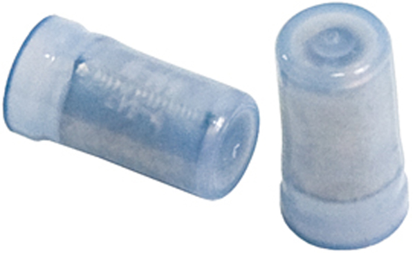
Modern avionics use multiple power and ground wires to reduce current through internal power circuits (reducing heat generated and extending the life of your avionics stack). Make your point to point wiring big enough to handle the total current requirement and then use a crimp type wire cap to splice the main power wire from the breaker to the two power input wires to the component. I typically do this a few inches before the tray connector and then lace it into the wire bundle so its not right where the shield drains are. The crimper used for PIDG ring terminals will crimp these also.
Last edited: