thibault
Member
- Joined
- Oct 25, 2009
- Messages
- 191
When I saw that V15.3.5 had "Added: Up to four discrete landing gear contacts now supported. Requires updated engine sensor definitions", I wanted that capability. To start with I already have dedicated 12V status lights through the Ray Allen indicator and did not want to give that up. I wanted redundancy and the audio warning from the Dynon.
I picked two more general purpose inputs, so I used EMS DB37 Pins 4, 10, and 11. You also have to get the new engine.sfg file to be able to select the sensor object. When I got that I did not like the names GEAR1, GEAR2 etc. You can change that to anything you want if you edit that .sfg and the .dfg files.
So I edited those text files and named the objects N_Gr, L_Gr, and R_Gr.
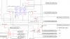
Then I connected the wires from pins 4, 10, and 11 to the points in the A/C wiring where the gear up/down status is ground while down and thought everything would be fine.
What happens is that the lights stay dimly lit when the gear is not down. Reason is that the selected points in the A/C wiring are +12V when the gear is not down and gnd when the gear is down. Remember that the contact object pins are pulled up to +5V in the EMS and the Dynon FW is looking for those pins to be essentially 5V or 0V. Since +12V minus +5V is still +7 volts, the 12V light is either dimly lit or brightly lit.
The solution is to put a diode between each of these EMS wires and the points selected in the A/C wiring selected.
All of this because my existing landing gear annunciation is wired such that +12V is supplied to the Ray Allen indicator and the lights in it light up when any of the six output wires see a ground. The ground happens, of course, when the gear is down and locked. The points I am sensing for the input to the EMS is where the wires comes out of the Ray Allen box. That point is either +12V or gnd.
If your wiring sends +12V to the position switch on the gear and then up to the light and then gnd, you would not have the problem that I had. You would connect the EMS sense wires to the input of the light (not the side that goes to gnd). That point would be +12V when the gear is down and gnd when it is not.
The attached schematic shows what I did
I picked two more general purpose inputs, so I used EMS DB37 Pins 4, 10, and 11. You also have to get the new engine.sfg file to be able to select the sensor object. When I got that I did not like the names GEAR1, GEAR2 etc. You can change that to anything you want if you edit that .sfg and the .dfg files.
So I edited those text files and named the objects N_Gr, L_Gr, and R_Gr.
Then I connected the wires from pins 4, 10, and 11 to the points in the A/C wiring where the gear up/down status is ground while down and thought everything would be fine.
What happens is that the lights stay dimly lit when the gear is not down. Reason is that the selected points in the A/C wiring are +12V when the gear is not down and gnd when the gear is down. Remember that the contact object pins are pulled up to +5V in the EMS and the Dynon FW is looking for those pins to be essentially 5V or 0V. Since +12V minus +5V is still +7 volts, the 12V light is either dimly lit or brightly lit.
The solution is to put a diode between each of these EMS wires and the points selected in the A/C wiring selected.
All of this because my existing landing gear annunciation is wired such that +12V is supplied to the Ray Allen indicator and the lights in it light up when any of the six output wires see a ground. The ground happens, of course, when the gear is down and locked. The points I am sensing for the input to the EMS is where the wires comes out of the Ray Allen box. That point is either +12V or gnd.
If your wiring sends +12V to the position switch on the gear and then up to the light and then gnd, you would not have the problem that I had. You would connect the EMS sense wires to the input of the light (not the side that goes to gnd). That point would be +12V when the gear is down and gnd when it is not.
The attached schematic shows what I did