Rotax 914 fuel flow configuration

oh-sdz

I love flying!
Joined
Mar 11, 2018
Messages
3
Hello,

I have SkyView system with EMS-220 connected to Rotax 914 motor.

Two topics:

1) Rotax 914 + two FT-60 fuel flow sensors.

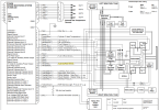
I am measuring motor fuel flow using two FT-60 fuel flow sensors as instructed in the SkyView System Installation Guide - Revision AB, page 7-59.

The inflow FT-60 is connected to pin 14 (yellow) and outflow FT-60 to pin 19 (white/black).

However, when motor is running and fuel flowing, the fuel flow reading is showing very high consumption as if SkyView was not measuring the differential fuel flow based on both sensors. I have measured that both sensors are giving the amount of pulses with oscilloscope, and calibration has been set to 68000 pulses.

SkyView software version is 14.2.1.3698.


2) Rotax 914 engine rpm measurement

There is a mistake in the SkyView System Installation Guide - Revision AB, page 7-48 saying:

"Do not install a resistor in the wires between the TCU and the SV-EMS-220".

First of all, Rotax 914 rpm information comes from Rotax 914 TCU pins 13 (rpm) and 26 (gnd).

Rotax 914 TCU pin 13 must be connected to EMS-220 pin 34 (Low voltage rpm input left), and Rotax 914 TCU pin 26 to ground.

Then, there has to be a 100 ohm load resistor connected between EMS-220 pin 34 and ground.

The 100 ohm load resistor is mentioned in Rotax 914 Installation Manual Edition 2 / Rev. 0, July 01/2008 page 125. However, this information has been omitted in new revisions.

RPM readings were erratic and not working at all without the 100 ohm load resistor even if RPM reading was connected to EMS-220 Standard RPM input.

I used oscilloscope to measure the real signal from Rotax 914TCU. The measured RPM signal from Rotax 914 TCU was 50 V impulses (2500 rpm) and it reduced to 8 volts with the load resistor.
 

Dynon

Dynon Staff
Staff member
Joined
Jan 14, 2013
Messages
14,231
Location
Woodinville, WA
On the fuel flow - have you looked at the sensor debug page under EMS setup? What do you see on the return sensor there?
 

oh-sdz

I love flying!
Joined
Mar 11, 2018
Messages
3
Both fuel flow sensor counters are increasing when I start fuel pump.
 

Dynon

Dynon Staff
Staff member
Joined
Jan 14, 2013
Messages
14,231
Location
Woodinville, WA
So as long as you have both fuel flow sensors, and they're both counting, flow should be right. What are the pulses per revolution set to for both? Regardless, see if loading this file helps at all. SkyView should already be treating those sensors as differential (rather than additive), but loading this file will make sure of that.
 

oh-sdz

I love flying!
Joined
Mar 11, 2018
Messages
3
So as long as you have both fuel flow sensors, and they're both counting, flow should be right. What are the pulses per revolution set to for both? Regardless, see if loading this file helps at all. SkyView should already be treating those sensors as differential (rather than additive), but loading this file will make sure of that.

I cannot find any file that was attached.

Both fuel flow sensors are configured to nominal 68000 pulses/gal.

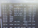
I don't know if it is normal but fuel flow reading jumps to about 30 when I start the pump and then the value evens out to exactly 0 when engine is not running. Value stays exactly at zero even at 4000 rpm.

It would great if future software versions could show also the individual sensor fuel flow rates next to the differential to be able to see that fuel pumps are working correctly. Also, resolution should have one more decimal to see at least some non-zero value when engine is idling.
 

Barry’s Phoenix

New Member
Joined
Feb 8, 2023
Messages
4
I am also having trouble with the duel sensor fuel flow on a Roatx 912ULS with 2 Red Cube sensors. I am getting very high flow readings like the return is not being accounted for.

First, the configuration file above did not work for me. It reported an Invalid Setting Line.

1676942430577.png


The file entry is:

ff_policy=SINGLE

which doesn't sound right to activate 2 sensors - but is not valid anyway!

This config file should not be need though, so; I am also unsure if my second sensor is working and I don't really understand what is reported in the diagnostics page. I am seeing some reading on the return P19 signal, but the all-zeros looks suspicious. If there was nothing I would say the sensor is not working, but it also measures less fuel so perhaps this is normal? Does this look like a correct/valid/reasonable diagnostic reading for the return sensor? This picture was taken when the engine was running.

1676942655232.png


Thanks for your help.
 

Attachments

  • 1676942614173.png
    1676942614173.png
    1.2 MB · Views: 101

Dynon

Dynon Staff
Staff member
Joined
Jan 14, 2013
Messages
14,231
Location
Woodinville, WA
I think the zeroes mean that there isn't anything being seen. That file above is erroneous though (now deleted). If you are running the latest experimental software, the fuel flow policy is always differential between the two sensors. IE, it always subtracts one from the other.
 

Barry’s Phoenix

New Member
Joined
Feb 8, 2023
Messages
4
I am still unable to get the second return flow sensor working. In flight I am getting silly-high flow readings, like 25 LPH from a 912. With the fuel pump running with the engine off, I expect to see readings on both sensors, but am only seeing readings on the main sensor in the debug screen. All zero on the return sensor. I swapped the sensors over (I have plugs on each sensor so can swap them easily) and still saw flow on ‘main’ which means the return sensor and its wiring is ok. (I.e return sensor plugged in to main input and saw flow on the main line) I buzzed the white/black wire from the return sensor plug back to pin 19 and that is fine. I checked the ground and power to the connector I have inline.

I can’t see anything else that could be the problem in the wiring.

So that leaves me wondering if I have missed something in the setup? I have mapped P19 as shown below. I called it return. Is there anything else I need to do to activate P19 as a fuel flow counter input?

Thanks again.

B0D595BA-CA9A-45B6-8DFB-6BDC373EBAA5.jpeg
 

Rhino

Well-Known Member
Joined
Jul 20, 2009
Messages
1,443
I don't claim to be greatly experienced in the engine area, especially Rotax, but based on the images in post 7, the Skyview doesn't even know you have a second sensor. That would explain a lot.

What is SETUP MENU > HARDWARE CALIBRATION > EMS CALIBRATION > FUEL FLOW CALIBRATION set to? Should be 68,000. And be aware, this must be done twice when using two fuel flow sensors. Be sure to press ACCEPT when you enter/change any of the PULS/GAL entries. Otherwise they don't take effect.

Do you have the sensors configured as per Figure 81 on page 7-61 of the current install manual (revision AM)?
 

Barry’s Phoenix

New Member
Joined
Feb 8, 2023
Messages
4
for the records:

After much debugging and fault finding ... we realised the plugs to the flow sensors had 5v on the signal pin of the sensor that was working, and 0V on the return sensor that is not working, suggesting it was not connected to the avionics.

(The sensors are open collector/pull down drivers with the recieving electronics having a pull-up resistor.)

The wiring buzzed OK to the plug, but we found the pin - #19 and at the end of the long row, was bent over in the EMS box so not connecting. It appears the plug was probably 'rolled in' from one end and caught the pin.

I have straightened the pin and now it is working correctly.

Thanks for the help.
 
Top