You are using an out of date browser. It may not display this or other websites correctly.
You should upgrade or use an alternative browser.
You should upgrade or use an alternative browser.
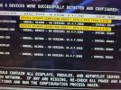
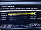
Skyview network connection fault
- Thread starter cbretana
- Start date
maartenversteeg
I love flying!
- Joined
- Oct 26, 2011
- Messages
- 241
The Dynon network is a redundant network providing a double /separate connection for the interfaces. When you get this message it means that the wiring is not providing a correct interface for the redundant interface on pins 4 & 8. The primary connection is working, as you say the servo's are working. But as part of the process the system also verifies if the backup connection is working, which according to the error message it isn't. You could operate like this but if the prinary link fails there is no longer a backup available. So the proper way would be to fix this and the error message suggests checking the wring of the pins 4 & 8 (measure continuity and ensure that all four pins are inserted correctly on both sides).
Does the fact that the message is only on the Servos indicate that the pin issue is on the the wiring for one (or both) of those components (the 2 AP Servos), and not on another different component?
Except for power, ground and A/P Disconnect wires, I have the network wiring for both servos spliced together so that they use only one DB-9 connector on the back of the display. I am thinking that it's in that one DB-9 that I should look first ?
Except for power, ground and A/P Disconnect wires, I have the network wiring for both servos spliced together so that they use only one DB-9 connector on the back of the display. I am thinking that it's in that one DB-9 that I should look first ?
maartenversteeg
I love flying!
- Joined
- Oct 26, 2011
- Messages
- 241
That's what it seems to suggest, it is most likely that the failure to communicate via the redundant interface is somewhere located in the common path. So either the connector on the back of the display or the shared wiring seems the most likely, but it could also be a consistent error in the wiring to each of the servo's. Verifying with a multi-meter that proper connections exist could be a first step after looking at the state of the connecter
All other network components access the display through a hub and thence to the other DB9 on back of display, and I still get same symptoms when I switch the two DB9s on back of display to use each other's port. So problem is probably either in that Common DB9 that both servos are using, or in wiring that goes to that DB9.
Thanks for your help! Merry Christmas.
Thanks for your help! Merry Christmas.
jakej
Well-Known Member
Post 3 alluded to a possible cause - check that the pins/sockets are seated fully (checked by a light pull on the wire) as a multimeter check will not show that, it will only show continuity -if you haven't already done this.
G'day I'm very interested in the outcome of your issue. I've just installed two SV32s but I'm only getting the Connection Fault for Pins 4 & 8 on one servo. Firstly I'm wanting to determine if the "DATA 2 PAIR (PINS 4 & 8)" is referring to the MOLEX connector pins or are is this referring to the pins for the serial autopilot connection? If it is the MOLEX connection then I'm even more puzzled as I've installed these into a Vans RV-12 and the wireing harness doen't have a connector wire/pin in MOLEX position 8 for either servo and the installation plans show that there is no wire for position 8???? I should note that I have not installed any knob control panel for the A/P at this stage.
ANY and ALL assistance will be greatly appreciated!
ANY and ALL assistance will be greatly appreciated!
Attachments
The DATA 2 pair, pins 4 and 8 are SV-Network D-9 pin numbers. You need to look at the RV-12 Electrical diagram for your version of the electronics to trace the wiring for those pins through the AV5000. Typically labeled as EFIS DATA G (SV-Net, pin 8) and EFIS DATA H (SV-Net, pin 4) are signal paths you want to trace. The two servos are on different AV5000 connectors, so identify the one that is working and then trace the other connector/cable for the issue. Could be a pin/socket not seated, broken wire or swapped G and H wires. Use the wires in the Molex of the servo that is working as a reference.


