You are using an out of date browser. It may not display this or other websites correctly.
You should upgrade or use an alternative browser.
You should upgrade or use an alternative browser.
SV-KNOB-DIMMER Questions
- Thread starter cbretana
- Start date
So I can attach the third wire of my potentiometer to aircraft ground and it should be consistent with the scheme you describe. But I don't understand what you mean by "Using only two wires, you take the strip completely out of the equation. " How so? It is then effectively the same as a rheostat. The strip is most definitely still in use. Because one of the two leads is attached to the slide moving back and forth on the resister. where it touches the resistor determines how much resistance the rheostat, (or the potentiometer with only two leads in use), creates. and as a result, how much voltage will be dropped across the two leads. What does attaching the other lead to ground do?
And as I understand it, (I am open to being corrected here), the HDX only uses the voltage sensed on pin 25 , (along with the Display Brightness settings in the configuration screen, and the ambient light sensor reading), to determine the brightness setting for the backlight. There is actually no current (or very little) flowing through pin 25. What small current might be flowing through pin 25 is used only to measure the voltage drop, it is not the current being fed to the lights themselves. Is that your understanding as well?
And as I understand it, (I am open to being corrected here), the HDX only uses the voltage sensed on pin 25 , (along with the Display Brightness settings in the configuration screen, and the ambient light sensor reading), to determine the brightness setting for the backlight. There is actually no current (or very little) flowing through pin 25. What small current might be flowing through pin 25 is used only to measure the voltage drop, it is not the current being fed to the lights themselves. Is that your understanding as well?
Last edited:
Rhino
Well-Known Member
- Joined
- Jul 20, 2009
- Messages
- 1,842
Using a potentiometer gives you two parallel paths, or legs, to ground, one straight through the potentiometer to ground and the other off the pickup lead through your load to ground. Both paths will always drop a total of 12 volts. That cannot be changed. Voltage in parallel is always equal to the total voltage. No matter what you do, there will always be 12 volts at the beginning and zero volts at the end of each leg. But current through individual parallel legs adds up to the total current. How much current each leg carries will vary with the total resistance of that leg. Resistance will change on your load leg when you adjust the potentiometer, so current will change with it. If you use a rheostat instead of a potentiometer, you now have only one leg to ground that must always carry full current. That could be a problem for the components in your load. If you use a rheostat, ALL your current will flow through pin 25. Not so with a potentiometer. You'll also never get zero volts at pin 25.
I apologize, but I still don't get it. If all you have is a resistance, (like a rheostat), in series with a 12v battery, and a load (like a bulb), the total voltage drop around the entire circuit must be zero, so the voltage drops across the resistance and the load must add up to 12 volts, right?
I understand about parallel. Using both output terminals on a potentiometer, the portion of the circuits from each of those two terminals to ground are, as you say, operating in parallel. But doesn't that mean that the current flowing through each of them is independant of the other, independently dependant on the impedance of that section of the circuit alone? And the voltage drops across each of them are just 12 volts less the voltage drop across the portion of the potentiometer resistence element that the lead was attached to in the pot, ( since the total voltage drop across both paths has to add up to 12 volts).
And why would it have to carry full current? What exactly do you mean by full current anyway? Won't the current be dependant on the resistance of the rheostat? If the rheostat is set to its highest impedance, (if that is high enough), no current will flow, right? The voltagecdrop across the rheostat will be 12 volts, and thee will be zero volts left for the rest of the path to ground, so the current will be zero.
Rhino
Well-Known Member
- Joined
- Jul 20, 2009
- Messages
- 1,842
Okay, I guess I miss my instructor days. Consider this diagram of four different circuits.

All circuits have 12 volts at the top and ground at the bottom, so they will all drop a total of twelve volts on each leg or path to ground. That cannot change.
Circuits A and B are series circuits. The total resistance of both circuits is 2.4 ohms, so they will both carry 5 amps of current, even though each resistor in circuit B drops an equal voltage that totals 12 volts.
Circuits C and D are parallel circuits. Each of the parallel legs has the same resistance as the single leg in A or B, but the circuit will carry 10 amps of current because current in each leg adds up instead of staying the same, as voltage does. You'd have to start changing resistance values to keep current under control.
Now let's add rheostats (or two leads of a potentiometer) into the mix.

Circuit E will carry all the amps you put into it when turned down to zero resistance, and pop your breaker, but will still carry 5 amps when turned up to 2.4 ohms. But that circuit doesn't control the voltage to a load like we need it to do.
Circuit F will now carry 10 amps when the rheostat is turned down to zero resistance because the overall resistance is now only 1.2 oms (0 on the rheostat and 1.2 on the load). It will carry 5 amps when the rheostat is turned up to full resistance, because overall resistance then goes up to 2.4 ohms. You are varying the voltage drop on the load as desired, but you're also radically changing the current through the load.
Now it gets really interesting. Circuit G uses a potentiometer instead. For the sake of demonstration, we'll leave the straight through resistance of the pot at 2.4 ohms on the right side. The resistance of the left leg is the load resistance added to the resistance you're getting off the pot in the right leg, giving you anywhere from 2.4 ohms (arrow all the way up) to 4.8 ohms (arrow all the way down) of total resistance through the left leg depending on where the pot is set. That still gives you a maximum of 10 amps in the overall circuit, but not through the load. It gives you anywhere from 2.5 to 5 amps through that leg, assuming my math is correct. Actually I think it's even less than that (I hate math, which is why I never became an engineer). In any case, the resultant current through the load is much better than the 10 amps we saw in circuit F, and that's far less damaging to sensitive electronic components. And you still control the voltage to the load exactly as you intended.
This gets even more interesting if you factor in that your load resistance isn't going to equal your pot value, and there are likely more components in the actual circuit than there are in these simplified diagrams. A 10k pot like you used radically alters the dynamics too. That's mainly why I always stick with potentiometers when engineers put them into a circuit.
Any of you engineer types out there can feel free to chime in here and tell me what I royally screwed up.
All circuits have 12 volts at the top and ground at the bottom, so they will all drop a total of twelve volts on each leg or path to ground. That cannot change.
Circuits A and B are series circuits. The total resistance of both circuits is 2.4 ohms, so they will both carry 5 amps of current, even though each resistor in circuit B drops an equal voltage that totals 12 volts.
Circuits C and D are parallel circuits. Each of the parallel legs has the same resistance as the single leg in A or B, but the circuit will carry 10 amps of current because current in each leg adds up instead of staying the same, as voltage does. You'd have to start changing resistance values to keep current under control.
Now let's add rheostats (or two leads of a potentiometer) into the mix.
Circuit E will carry all the amps you put into it when turned down to zero resistance, and pop your breaker, but will still carry 5 amps when turned up to 2.4 ohms. But that circuit doesn't control the voltage to a load like we need it to do.
Circuit F will now carry 10 amps when the rheostat is turned down to zero resistance because the overall resistance is now only 1.2 oms (0 on the rheostat and 1.2 on the load). It will carry 5 amps when the rheostat is turned up to full resistance, because overall resistance then goes up to 2.4 ohms. You are varying the voltage drop on the load as desired, but you're also radically changing the current through the load.
Now it gets really interesting. Circuit G uses a potentiometer instead. For the sake of demonstration, we'll leave the straight through resistance of the pot at 2.4 ohms on the right side. The resistance of the left leg is the load resistance added to the resistance you're getting off the pot in the right leg, giving you anywhere from 2.4 ohms (arrow all the way up) to 4.8 ohms (arrow all the way down) of total resistance through the left leg depending on where the pot is set. That still gives you a maximum of 10 amps in the overall circuit, but not through the load. It gives you anywhere from 2.5 to 5 amps through that leg, assuming my math is correct. Actually I think it's even less than that (I hate math, which is why I never became an engineer). In any case, the resultant current through the load is much better than the 10 amps we saw in circuit F, and that's far less damaging to sensitive electronic components. And you still control the voltage to the load exactly as you intended.
This gets even more interesting if you factor in that your load resistance isn't going to equal your pot value, and there are likely more components in the actual circuit than there are in these simplified diagrams. A 10k pot like you used radically alters the dynamics too. That's mainly why I always stick with potentiometers when engineers put them into a circuit.
Any of you engineer types out there can feel free to chime in here and tell me what I royally screwed up.
Last edited:
Marc_J._Zeitlin
Active Member
Only here - you meant to say "zero volts" at the bottom (being ground, and all), not 12V at the bottom (in which case absolutely nothing would happen on any of the circuits... All circuits have 12 volts at the top and 12 volts at the bottom, so they will all drop a total of twelve volts on each leg or path to ground. That cannot change....
Any of you engineer types out there can feel free to chime in here and tell me what I royally screwed up.
") .
.Rhino
Well-Known Member
- Joined
- Jul 20, 2009
- Messages
- 1,842
I probably didn't explain that well, but consider the opposite of your example. Turn the rheostat off so that it has zero resistance. It essentially becomes a straight piece of wire. The load now carries the entire circuit current. I really don't know what that current might be, because I don't know the values of the components behind pin 25. But the engineers at Dynon do, and by all appearances they use a potentiometer in their dimmer. I will opt for the knowledge and experience they used in coming to that decision.....If the rheostat is set to its highest impedance, (if that is high enough), no current will flow, right? The voltagecdrop across the rheostat will be 12 volts, and thee will be zero volts left for the rest of the path to ground, so the current will be zero.
EDIT: I know you meant resistance rather than impedance, so I ignored that. Don't EVEN get me started on inductors and impedance!
Last edited:
Rhino
Well-Known Member
- Joined
- Jul 20, 2009
- Messages
- 1,842
Doh!!! Thanks.Only here - you meant to say "zero volts" at the bottom (being ground, and all), not 12V at the bottom (in which case absolutely nothing would happen on any of the circuits
Excellent diagrams! Thanks!
But your circuit "G" is different than what I thought. I am under impression that the slider terminal is the one that brings the full 12 volts into it, and the two other terminals on the pot are attached to the ends of the resistence element. That way, the pot acts as a voltage "splitter". Depending on where on the resistence element that the slider touches, the outputs paths include one side of the resistence or the other side.
Your diagram G has the 12 volts coming in from one end of the resistence, not from the slider.
I hooked up an ohmmeter to my potentiometer, and measured the impedance across the terminals as I rotated the knob. The impedance across terminals 1 & 3 was a constant 10k. The impedance across 1&2 varied from zero to 10 k as I rotated the knob clockwise, and across 2&3 it varied from zero to 10k as I rotated the knob counterclockwise.
That indicated to me that the 12 volts source should be connected to the slider, not to one end, and I should tap one of the ends to go to the Dynon pin 25. And that I should choose the end where the resistance goes from max (10 k ohms), so i will get close to zero volts on pin 25, to zero, (so i will get the full 12 volts), as I rotate the knob clockwise, so that rotating the knob clockwise will increase the brightness. That's what I did, and I did get that result.
That indicated to me that the 12 volts source should be connected to the slider, not to one end, and I should tap one of the ends to go to the Dynon pin 25. And that I should choose the end where the resistance goes from max (10 k ohms), so i will get close to zero volts on pin 25, to zero, (so i will get the full 12 volts), as I rotate the knob clockwise, so that rotating the knob clockwise will increase the brightness. That's what I did, and I did get that result.
Okay, but, the way you have it depicted, the impedance to ground on the right side is a constant 2.4 ohms, the way I was envisioning it, the impedance on the path to ground would be the total impefance acriss the entire element, ( 2.4 ohms), less whatever impedance is drawn by the other, (left hand) side.
This would make a big difference. If i wire it the way i was thinking, when i rotate the knob full counterclockwise, setting the impedance on the output path (to pin 25), to its maximum 10k ohms, the path to ground would be a short circuit. That would definitively not be advisable.
This would make a big difference. If i wire it the way i was thinking, when i rotate the knob full counterclockwise, setting the impedance on the output path (to pin 25), to its maximum 10k ohms, the path to ground would be a short circuit. That would definitively not be advisable.
Last edited:
Where pin 2 is the one commonly called the slider?
Right now, as I have it wired, I think I have pin 1 on the pot going to pin 25 on the Skyview HDX, and 12 volts going into the slider. I will need to reverse those to do the wiring as you recommend.
But I confess, I still don't understand what the right side of your circuit G does. The left side should not behave any differently, with or without that right side connected to ground.
Last edited:
Rhino
Well-Known Member
- Joined
- Jul 20, 2009
- Messages
- 1,842
Yes.Where pin 2 is the one commonly called the slider?
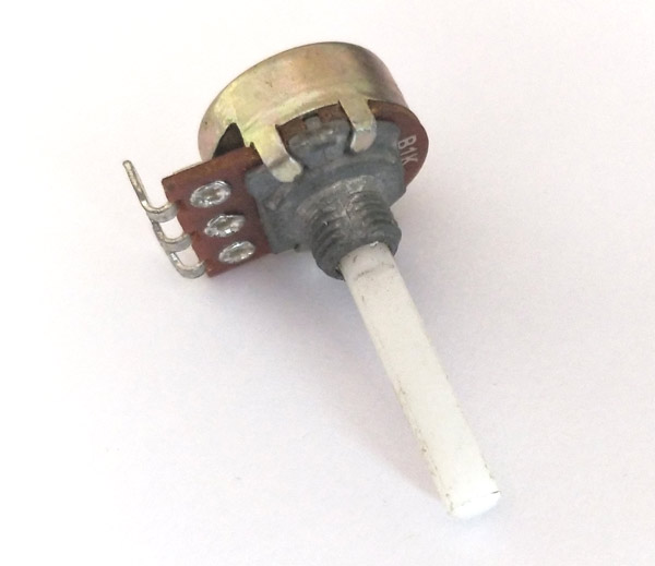
In diagram G, the resistance between 12 volts at the top and ground at the bottom will always be 2.4 ohms and will always drop 12 volts. That will never change. That's why those are depicted as non-adjustable inputs on the diagram (no arrow). The line with the arrow adjusts (changes), so it outputs the control, or reference, voltage to your load. You want the changing voltage to go to your load. That's why it's depicted that way. There are different types of potentiometers, including solid state, but most used to use a resistive coil or track that a slider rides on. Many of them are still built that way. You can see a representation here:

I found this, on Wikipedia:
One of the advantages of the potential divider compared to a variable resistor in series with the source is that, while variable resistors have a maximum resistance where some current will always flow, dividers are able to vary the output voltage from maximum (VS) to ground (zero volts) as the wiper moves from one end of the potentiometer to the other. There is, however, always a small amount of Contact Resistance.
For the function of dimming the Skyview screen, we need to inject a voltage on pin 25 between zero and some specified maximum (which is specified in the Display Brightness setting).
So, in order to allow access to the complete range of necessary voltages from zero all the way to the naximum, (12 volts in my aircraft), it is necessary to use a potentiometer rather than a variable resistor (rheostat).
Last edited:
I have modified the wiring as you outlined in diageam G, and there was a noticeable improvement in both the low, fully counterclockwise end (it's now dimmer than it was), and in the high (full clockwise) end (it's way brighter).
Thanks for your time in helping with this. I would never have figured this out on my own. The first web site I read about potentiometers described it as a "voltage splitter", which would require the 12volt input on the center slider pin, and two outputs one on each end of the resistance. That's the only way to wire it to accomplish that. It would "split" the input voltage into two parts, depending on where you position the slider. In the middle, there would be six volts on each end. Positioned a quarter of the way there would be 3 volts kn one end and 9 on the other. This flawed assumption about what pins the three wires had to be connected to was a large part of my confusion.
But there's no way to connect an end to ground if you wire it that way. To do the ground thing you have to put the 12 volt input on one end contact and attach the variable output to the center slider pin.
Again, thanks for your time!
Here's my panel with the potentiometer above top right edge of the HDX screen, just right of the low battery light.