Two independant Fuel Flow Senders

steve_izett

New Member
Joined
Jun 10, 2018
Messages
14
Location
Perth Western Australia
Hi there.
Can I use the the two fuel flow sender inputs independently? eg. One for engine fuel flow, the other for transfer from one tank to another.
Also I notice the K factor appears to have a minimum of 10,000. IS this correct? I have a sender that produces about 950 pulses/gal.
Any help appreciated.

Steve
 

Dynon

Dynon Staff
Staff member
Joined
Jan 14, 2013
Messages
14,232
Location
Woodinville, WA
You can, but you need to use special config files to enable it. They're attached. The "separate" one unlinks the two sensor inputs. The "differential" one reattaches them
 

Attachments

  • Fuel_Flow_Differential.dfg
    17 bytes · Views: 256
  • Fuel_Flow_Separate.dfg
    17 bytes · Views: 258

Dynon

Dynon Staff
Staff member
Joined
Jan 14, 2013
Messages
14,232
Location
Woodinville, WA
As for the question of the pulses - not sure. There are two line items in the config file that govern this, which are nominally set by the on-screen user interface. Those are:

pul/gal_1=68000
pul/gal_2=68000

...where you replace the 68000 with the number of your choosing. Normally, the on-screen UI doesn't let you go below 10000, as you've found, but I *think* if you load it from a file with a number, it may use it as-is. I can't test at the moment (not in front of a unit). Let me know if you need files to try if you're not a computer person.
 

steve_izett

New Member
Joined
Jun 10, 2018
Messages
14
Location
Perth Western Australia
Hi there Dynon Staff.
I finally got around to changing the pul/gal_2 to 950 in the user config file instead of the 10000 forced by the UI.
Yes it did work. The second Fuel Flow display is correct and used the K factor from the config file.

However for some reason on the next flight the Fuel Computer recorded Fuel Used being much higher than the displayed Fuel Flow from the Primary Fuel Flow Sender, and naturally, Fuel Remaining dropping at an similar yet astounding rate.

The Config File copy and paste -

ff_policy=SINGLE
pul/gal_1=32750
pul/gal_2=950

The only thing I changed (pretty sure) was the pul/gal_2 figure, from 10000 to 950.
The independent (ff-policy=SINGLE) second Fuel Flow Sensor data has gone up by a factor of over 10x which seems to be reflected in the FUEL COMPUTER fuel used.
Could the Fuel Computer be summing the two Fuel Flow Senders?
Any insights would be appreciated.

Cheers
 

Dynon

Dynon Staff
Staff member
Joined
Jan 14, 2013
Messages
14,232
Location
Woodinville, WA
Yeah, I think you're right. If you use two flow sensors, they're both assumed to be carrying fuel to the engine, and I believe they get summed.
 

steve_izett

New Member
Joined
Jun 10, 2018
Messages
14
Location
Perth Western Australia
So we can't use the 2 fuel flow inputs independently??

I wanted:

Fuel Flow 2 to monitor fuel flow from the 40 Gal wing tank to the 8 Gal header/reserve tank which overflows back to wing tank.
An alarm on low flow warns of either 1. Main Wing Fuel is empty OR 2. Transfer Pump has failed.

Fuel Flow 1 measures fuel flow from the Header/Reserve Tank to the Engine.

What about the 'split_fuel_comp=0' in the User Config? I thought this was probably for multi - engine/EMS setups but could it help me?

Thanks very much.
Steve
 

steve_izett

New Member
Joined
Jun 10, 2018
Messages
14
Location
Perth Western Australia
Hi Dynon.
What does the "split_fuel_comp=0" in the User_Config do?
I would still be a significant outcome for me to be able to use the 2nd Fuel Flow input independently, and not be factored by the Fuel Computer as I stated above.
Help would be much appreciated.
Thanks
Steve
 

Dynon

Dynon Staff
Staff member
Joined
Jan 14, 2013
Messages
14,232
Location
Woodinville, WA
Actually, there's an option under the dual engine setup menu that lets you split the fuel in dual engine setups in two. That toggle in the menu affects that setting. This will only work with dual EMS module setups though, I think.
 

jaredyates

Member
Joined
Jan 29, 2016
Messages
58
Location
Hickory, NC
I'm resurrecting an old thread here, but has anyone had any success with running two EI fuel flow sensors into a single fuel flow output, either through the Dynon or otherwise? I need to run two sensors for flow reasons. I don't know why they only make them with such tiny holes! So I have one sensor for the left tank, and one sensor for the right tank. While it would be cool to be able to display those two separately, what I am really after is just how much fuel is going to the engine, or a summing of the two sensors. After reading this thread I have created the fuel system, but now support says that there is not a way to add the two together. This seems contrary to what the thread here says. This is a case where I'm going to need to make it happen one way or another, but would hope to find someone else who has already been down the road rather than having to craft a solution myself.
 

Marc_J._Zeitlin

Active Member
Joined
Sep 24, 2007
Messages
318
Location
Tehachapi, CA 93561
... I need to run two sensors for flow reasons. I don't know why they only make them with such tiny holes! So I have one sensor for the left tank, and one sensor for the right tank. While it would be cool to be able to display those two separately, what I am really after is just how much fuel is going to the engine, or a summing of the two sensors...
I'm not sure what engine you're running, but the FT-180 is good up to 250 GPH, which I'd imagine is good enough for almost any piston engine out there and many turboprops. You don't need two senders if you're under 250 GPH.


and the FT-90 can deal with up to 125 GPH, so that should be more than adequate as well:


jaredyates

Member
Joined
Jan 29, 2016
Messages
58
Location
Hickory, NC
Thank you for your willingness to help, but the problem isn't the maximum rated fuel flow through the sensor, it's the actual fuel flow through the sensor. With no sensor in the line I get 47 gph, and with the single gold cube sensor I get 34 gph. I need 40.
 

Marc_J._Zeitlin

Active Member
Joined
Sep 24, 2007
Messages
318
Location
Tehachapi, CA 93561
Thank you for your willingness to help, but the problem isn't the maximum rated fuel flow through the sensor, it's the actual fuel flow through the sensor. With no sensor in the line I get 47 gph, and with the single gold cube sensor I get 34 gph. I need 40.
Ummm, then you're using the wrong sensor. Since the FT-90 can flow 125 gph and the FT-180 can flow 250 gph, either one will be more than adequate for your 40 gph required flow rate. Although the FT-60 can nominally flow >60 GPH, it's possible that your pump can't deal with the pressure drop that that would entail. So use a larger sensor - you're close to what you need, so the next size up would do the trick.
 

jaredyates

Member
Joined
Jan 29, 2016
Messages
58
Location
Hickory, NC
There are no pumps, thanks again for your willingness to help but I have tried to ask a pretty specific question to address a pretty specific need here.
 

Marc_J._Zeitlin

Active Member
Joined
Sep 24, 2007
Messages
318
Location
Tehachapi, CA 93561
There are no pumps, thanks again for your willingness to help but I have tried to ask a pretty specific question to address a pretty specific need here.
Why don't you explain your fuel system setup and what you're trying to do, and maybe you'll get an answer that's more to your liking. Just saying "the holes in the senders are too small" is a meaningless (and incorrect) claim, so more information would be useful in assisting you in your quest.
 

jaredyates

Member
Joined
Jan 29, 2016
Messages
58
Location
Hickory, NC
It fascinates me that you feel like I have to validate my standing to be able to ask a question for you. If you don't know the answer for how to take the inputs from two EI fuel sensors and make them display a flow rate on the Skyview, that is ok, I don't either. But if that is the case, why are you replying here?

My fuel system is a carbureted high wing airplane with no fuel pumps. That is because there is apparently no pump on the market that meets my design criteria, which is a port size of at least 3/8", no check valves or other flow restrictions when it is off, and a pressure of around 5psi. Can you call out one? If you can, by all means please do, that will be helpful.

The holes in the fuel flow sender are absolutely too small for my application, whether or not you want to argue about that. I have a half inch fuel line which delivers plenty of flow until I put a sensor in it, because the sensor uses 1/4" ports and an even smaller central orifice. If I put two sensors farther upstream of the fuel valve (one for the left and one right tank) where I have two 3/8 lines, the losses are acceptable.

So again, I have asked a pretty specific question for a pretty specific need, and while I appreciate that you are trying to help, I am beginning to doubt that you are going to be able to help if you can't first get past your need to undermine the premise of my specific question, for reasons that aren't apparent to me, other than that perhaps you like arguing.
 

Marc_J._Zeitlin

Active Member
Joined
Sep 24, 2007
Messages
318
Location
Tehachapi, CA 93561
Had you stated the information above in your first posting, I would probably have ignored you. But since the 250 gph sensor that I pointed you to (the FT-180) has a pressure drop of only 0.23 psi at a flow of 60 gph (50% more than you're looking for) and a pressure drop of only 0.92 psi at 120 gph (3X your desired flow rate) and can do everything you want (low pressure drop at high flow rate) with only ONE sensor, maybe you should pay attention, since I've solved your problem in a way that you hadn't anticipated.

Good luck. I see that no-one else has responded - maybe I should have done the same, as you don't seem open to evaluating other possible solutions than the one on which you are fixated.
 

airguy

Well-Known Member
Joined
Nov 10, 2008
Messages
1,069
Location
Gods Country - west Texas
Marc is right. Given the data you have supplied, the sensors will work just fine. Whether you choose to accept that or not is up to you. There may be other circumstances that may make those sensors unacceptable for one reason or another, but you are clearly unwilling to share that information, so this is as far as we can help you.

Best of luck.
 

jaredyates

Member
Joined
Jan 29, 2016
Messages
58
Location
Hickory, NC
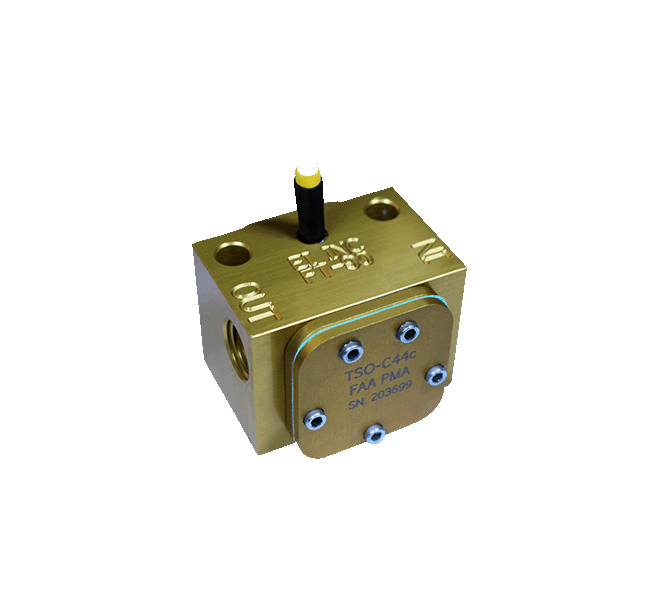
It's not that I didn't anticipate the FT-180 working- I evaluated and decided against that possibility before I came to post here, for reasons that are still true. The first one is that I don't have an FT-180 to test with, and don't want to conduct a $450 experiment just to see if it would work. The second one is that while the black cube has 50% less pressure loss at the internal passages than the gold cube, it still has a reduction from half inch lines (ID .430") down to quarter inch pipe thread fittings, which also lead to a further loss. Have you accounted for that loss in your calculations?

I appreciate your encouragement that it should work, but you also seem pretty sure that a single gold cube should work, which actual testing showed that it does not work. In the end I need an actual flow rate delivered out of the end of the fuel line, and while the theory helps get close to a final solution, the results are what matters. If anyone would like to loan me one I'm happy to test it. EI is not willing to loan me one, I didn't expect them to but did ask just in case they were.

So with the distractions hopefully out of the way and getting back to the reason for my post, there are three possible scenarios that I can think of to solve the question of feeding the input of two sensors into the Skyview.

Option 1: Maybe support is wrong and the thread is right, and the software can actually do it. Pin 19 is still listed in the install manual as a second fuel flow input. This would be somewhat easy to test at least, with a temporary wire initially.

Option 2: EI makes a separate piece of hardware (FFAM) that will consolidate the two sensors into a single output which can then run to the EMS as usual. It's $200 and seems to be only available from them, which isn't so bad if it works the first time and never needs to be replaced. If it breaks, it is a black box.

Option 3: It seems plausible to create an Arduino-based extra hardware device that could consolidate the two signals. The disadvantage is more development time vs the EI FFAM. The total materials cost with a name-brand processor is around $50 (half is the processor) which is much more favorable in explicit terms than the EI. The biggest advantage would be that I would know how it works in case it ever needed replacement, tweaking, or other repair, though I would hope that either option would be low risk for developing problems.

The one big downside of my current iteration, which delivers at total of 42 gph through the two gold cube sensors (one on each tank output), is that there is potential error if fuel flows across the valve from the left to the right tank. Since the sensor doesn't know whether fuel is flowing forward or backward, any cross-flowing fuel will be counted twice, in addition to any fuel that is going to the engine. This error would be momentary as it relates to the engine flow rate, but could end up being a factor in using the fuel flow to derive a fuel remaining on board solution and I'd probably end up breaking that widget. At least it would indicate lower than actual rather than the other way around.

One solution to that issue would be to route the output from the fuel valve into the two gold cubes parallel, but with all of the fittings and direction turns that this would require, I worry that the flow loss would be too impactful.
 

jaredyates

Member
Joined
Jan 29, 2016
Messages
58
Location
Hickory, NC
Here is today's update. I temporarily wired the two cubes with one on pin 14 and one on pin 19. If I go to the sensor debug data and manipulate the fuel valve so that fuel flows out of the tanks and into a fuel can, I can definitely see good fuel flow numbers on p14 and p19. The output of the sensors is getting into the Skyview for sure. The left cube is on pin 14 and the right cube is on pin 19. However, the fuel flow widget on the EMS is showing the difference between the two.

If I go to the EMS screen setup and try to add a widget for the new sensor, it does not populate in the list.

If I try to add a .dfg file with the "ff_policy=SINGLE" line, the result is that the line is invalid.

So my takeaway here is that support was correct, they have removed previously available functionality to sum two fuel sensors. The system still does work to subtract the values of the two. But the top half of the thread has been superseded by this decision to remove the function. This is an unfortunate choice, but I guess unless I want to start my own avionics company I'm stuck with their whims.

My next step is going to be to try the Arduino to consolidate the two outputs. If that doesn't work or gets to be too sketchy then I'll look further into the commercially-available option.

I was also able to find y-shaped AN-style fitting that has a half inch input and two 3/8 outputs, so I will order two of those and see if I can construct a system with the two cubes in parallel, downstream of the fuel valve and gascolator. This will be easy to test, and if I can get sufficient flow, it will be superior to the current arrangement because it will eliminate the possible cross flow error. These y fittings seem much more likely to flow than all of the t-fittings and elbows I was imagining before.
 

Rhino

Well-Known Member
Joined
Jul 20, 2009
Messages
1,539
What ever happens with your situation, Jared, I want to thank you for providing all the detailed troubleshooting details and results. They serve as an excellent resource for people who come here later on looking for information. And unfortunately, too many people don't share the details, or even the resolution for, the problems they post here.
 
Top