External Dimmer Pin 25 and 26

Dynon101

I love flying!<br />
Joined
Mar 5, 2016
Messages
382
Hi All,

Getting closer to SkyView Bliss...

Can you please confirm my wiring plan for the following system:

-Dual SV-1000
-RockRack switches with switch face LED that illuminates when the switch is ON.
-Ten OHM potentiometer

I want the SV displays to dim and my switch face LEDs to also dim using an external potentiometer.

This is the potentiometer I bought:
https://www.amazon.com/gp/product/B009QFU9H4/ref=oh_aui_search_detailpage?ie=UTF8&psc=1

The wiring for the RockRack switches is that when the switch is placed in the ON position the electrical power is provided to wire that runs to the appliance (electric fuel pump) and also branched off of that powered wire is a second wire that loops back to the switch and flows to the POS side of the switch face LED. If the NEG side of the LED is grounded then the LEDs will be full bright and I do not want that.

Here is my plan:

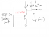
From PINs 21 and 22 of PILOT SV a BLACK wire will run to the #1 terminal (outside) of POT

From PINs 1 and 20 of PILOT SV a red wire will run to the #3 (other outside) terminal of POT

From the center terminal of the POT I will run a violet wire to PIN 25 of the PILOT SV and also run a jumper wire to PIN 25 of the COPILOT SV.

From the NEG terminal of all of the switch face LEDs I will connect them all together into one YELLOW wire and run that single wire to PIN 26 of ONLY the PILOT side SV .

Will that do the trick???

THANKS FOR YOUR HELP!!!

::) ::) ::) ::) ::) ::) ::) ::) ::) ::) ::)
 

Dynon101

I love flying!<br />
Joined
Mar 5, 2016
Messages
382
Dynon Tech Support would you PLEASE be so kind as to answer this question?
 

vlittle

Active Member
Joined
May 7, 2006
Messages
524
Dynon Tech Support would you PLEASE be so kind as to answer this question?

In defense of Dynon, they cannot design everyone's electrical system for them.  That's why avionics shops and people like me exist.

However, your application is common enough to be addressed.  The Dynon dimmer outputs may not be able to drive the load you want.  You will want a buffer between the SV and your lamp common connection.

I'd recommend a PNP transistor of appropriate rating for the lamp driving.  See attached file as an example.  You will need to choose the right transistor for the total load.
Cheers, Vern
 

Attachments

  • IMG_0771.PNG
    IMG_0771.PNG
    249.7 KB · Views: 341

swatson999

Well-Known Member
Joined
Oct 6, 2010
Messages
1,496
If I might add a comment...I have a SV1000T and the RockRack switches, but I have no external dimmer control on either. The SV auto dimming functions works quite well, and the switches have never been bright enough at night to be of any concern...in fact, if anything, I'd prefer them to be brighter during the day.

Everyone can design their own system, but FWIW, the simplest way (let SV handle its brightness level automatically, and just hook up the switches with no dimmer) works just fine for me. And its one (or two) fewer things to fail. YMMV.
 

Dynon101

I love flying!<br />
Joined
Mar 5, 2016
Messages
382
Vern-X, Thank you for your time and the schematic you wrote up.

I did not want Dynon Tech Support to design my system I do however would like them to verify that my wiring plan is accurate because the text of the manual is not clear enough for me to understand the system.

Dynon. Tech support can you please verify my wiring olan based on my original post?
 

dynonsupport

Dynon Technical Support
Staff member
Joined
Mar 23, 2005
Messages
13,226
You are asking us to design a lot.

Page 4-33 says this. What is unclear?

DIM OUTPUT (Pin 26) The DIM OUTPUT signal is an approx. 120 Hz (may change in future
Software revisions) Pulse Width Modulation (PWM) signal directly proportional to the screen
brightness – 100% to 0.02%. This output is designed to directly control the dim level of devices
such as LEDs; a common use is for the back-lighting of switches in a panel so that they dim at
night in conjunction with SkyView’s automatic dim levels.

The DIM OUTPUT (Pin 26) signal is an open collector to ground - it acts as a switch to ground,
and does not source any power itself. Pin 26 can sink a maximum current of 120mA and a
maximum voltage of 40V. The DIM OUTPUT signal is not analog and cannot be used to control
the dim level of devices that expect 0-5V, 0-12V, or a resistance as their dimming input.

Do not connect the DIM OUTPUT (Pin 26) signal from multiple SkyView screens in parallel. The
DIM OUTPUT signals from each display is not synchronous, and this will lead to inconsistent
behavior.
 

vlittle

Active Member
Joined
May 7, 2006
Messages
524
The SV can drive up to six RockRack switches directly. For more than that, the buffer circuit I drew should work, for up to 20 or so switches.

Vern


You are asking us to design a lot.

Page 4-33 says this. What is unclear?

DIM OUTPUT (Pin 26) The DIM OUTPUT signal is an approx. 120 Hz (may change in future
Software revisions) Pulse Width Modulation (PWM) signal directly proportional to the screen
brightness – 100% to 0.02%. This output is designed to directly control the dim level of devices
such as LEDs; a common use is for the back-lighting of switches in a panel so that they dim at
night in conjunction with SkyView’s automatic dim levels.

The DIM OUTPUT (Pin 26) signal is an open collector to ground - it acts as a switch to ground,
and does not source any power itself. Pin 26 can sink a maximum current of 120mA and a
maximum voltage of 40V. The DIM OUTPUT signal is not analog and cannot be used to control
the dim level of devices that expect 0-5V, 0-12V, or a resistance as their dimming input.

Do not connect the DIM OUTPUT (Pin 26) signal from multiple SkyView screens in parallel. The
DIM OUTPUT signals from each display is not synchronous, and this will lead to inconsistent
behavior.
 

Dynon101

I love flying!<br />
Joined
Mar 5, 2016
Messages
382
Dynon Tech Support,

Your website states "A SINGLE FOCUS ...stand behind our products with the industry's best support.

I did NOT ask you to design anything. 

Please understand that I have bought THOUSANDS OF DOLLARS OF EQUIPMENT FROM YOUR COMPANY and the salesperson said that you will provide help and support.

I imagine that customers like me enable you to provide for your family and in return I ask that you PLEASE be professional and treat me with respect and answer my above question.

A simple YES or NO (and provide the correct method to install the dimmer circuit) answer to my tech support question would have been a more PROFESSIONAL way to deal with a customer than a dissapointing response of reprinting the text from the Installation Manual...yes I DID INDEED read it...however...I did not fully understand and that is why I asked the question.


Vern,

I am VERY GRATEFUL for your kind assistance.  I did not receive instructions with the RockRack switches so I did not know the LEDs were 20 milliamps and therefore the SV could only sink 6 switch LEDS.

Your schmatic is very helpful.  The 2N2907A transistor you recommend has the poles.  Can you PLEASE let me know what pole is ground, LED NEG side, and SV Dimmer OUt.

Also, when you state "SV DIMMER OUT" can you please confirm you are referring to PIN 26.

THANKS AGAIN!!!
 

krw5927

I love flying!
Joined
Mar 1, 2015
Messages
124
A bit of unfair vendor bashing here.  You have sourced random components from random places and expect Dynon to research the electrical characteristics of the components you purchased.  You also provided incorrect information about at least one of the components you sourced, stating in the first post that you purchased a "10 OHM" potentiometer but providing a link to a 10k Ohm pot.  HUGE difference - one will smoke and self-destruct when connected across a 12V source, the other will not.  But I only know that because I took the time to click on your link.

If you need custom electrical design performed, there are lots of people out there who will be happy to help.  Some, like Vern, graciously help people out for free when able.  Others may charge for their services, and rightfully so.  Expecting Dynon to bake that level of support into their pricing is unfair.

Dynon Tech Support,

Your website states "A SINGLE FOCUS ...stand behind our products with the industry's best support.

I did NOT ask you to design anything. 

Please understand that I have bought THOUSANDS OF DOLLARS OF EQUIPMENT FROM YOUR COMPANY and the salesperson said that you will provide help and support.

I imagine that customers like me enable you to provide for your family and in return I ask that you PLEASE be professional and treat me with respect and answer my above question.

A simple YES or NO (and provide the correct method to install the dimmer circuit) answer to my tech support question would have been a more PROFESSIONAL way to deal with a customer than a dissapointing response of reprinting the text from the Installation Manual...yes I DID INDEED read it...however...I did not fully understand and that is why I asked the question.
 

mrdaud

Member
Joined
Sep 28, 2009
Messages
122
To HomeBuilt101 - Dude! Agree with krw5927. it is not Dynon's responsibility to review or approve any non-Dynon hardware. The Dynon install manual provides more than enough information to support external dimming for anyone with basic electronics knowledge.

Also, and I say this with all due respect, if you don't know the difference between a PNP and NPN transistor, or know how to read pin designations on transistors, you should have someone else do your circuit building for you. Otherwise, I see future smoke in your cockpit! Not trying to be mean, just realistic. There should be someone like Vern at your local EAA chapter to help. There are also lots of chat sites with electronic geeks that would be happy to help you out.
 

dynonsupport

Dynon Technical Support
Staff member
Joined
Mar 23, 2005
Messages
13,226
As a side note, you can't hook a 10 ohm pot across the aircraft power. This will draw 1.4 amps, 20watts, and will possibly catch on fire.
 

Dynon101

I love flying!<br />
Joined
Mar 5, 2016
Messages
382
>There are also lots of chat sites with electronic geeks that would be happy to help you out.

Yes... those "electronic geeks" on the premier experimental electronic aviation forum are substantially more helpful and supportive than the Dynon Tech "Support" people on the Dynon Tech Support forum ...

Surprisingly I have read countless posts on this forum where Dynon has answered very complex questions about integration with very complicated third party avionics equipment... and then it is most frustrating and disappointing that Dynon Tech Support would not answer a simple wiring question... let alone promote a positive communication environment.

Sadly I thought this was the place to ask questions so that owner/builders can have a positive and SAFE user experience with the Dynon equipment... and... perhaps even have such a positive experience that they would recommend Dynon to their friends.

I am perplexed and I still wonder why it is so difficult about answering with "yes that will work" or "no that will not work because..." or "please call us to discuss farther".

Can someone who is positive and courteous please answer my original question about the wiring?
 

vlittle

Active Member
Joined
May 7, 2006
Messages
524
Here's a link to a datasheet http://www.mccsemi.com/up_pdf/PN2907A(TO-92).pdf

That should give you the info you need for wiring, but you'll be dealing with soldering and mounting.  There should be some guy nearby nicknamed 'Sparky' who can help you. What I would do if it were me would be to solder the transistor to a 15 pin DSub connector (solder cup type) and bus all of the lamp connections together on the connector pins with a piece of wire. This is now your 'gizmo'.
Then, using a mating connector you can provide the PWM signal, ground and the lamp connections permanently wired to the aircraft.  Plug your gizmo into this connector.

You can also enclose the connectors with backshells to protect the wiring.

Pin 26 is the dimmer out.

Vern


Dynon Tech Support,

Your website states "A SINGLE FOCUS ...stand behind our products with the industry's best support.

I did NOT ask you to design anything. 

Please understand that I have bought THOUSANDS OF DOLLARS OF EQUIPMENT FROM YOUR COMPANY and the salesperson said that you will provide help and support.

I imagine that customers like me enable you to provide for your family and in return I ask that you PLEASE be professional and treat me with respect and answer my above question.

A simple YES or NO (and provide the correct method to install the dimmer circuit) answer to my tech support question would have been a more PROFESSIONAL way to deal with a customer than a dissapointing response of reprinting the text from the Installation Manual...yes I DID INDEED read it...however...I did not fully understand and that is why I asked the question.


Vern,

I am VERY GRATEFUL for your kind assistance.  I did not receive instructions with the RockRack switches so I did not know the LEDs were 20 milliamps and therefore the SV could only sink 6 switch LEDS.

Your schmatic is very helpful.  The 2N2907A transistor you recommend has the poles.  Can you PLEASE let me know what pole is ground, LED NEG side, and SV Dimmer OUt.

Also, when you state "SV DIMMER OUT" can you please confirm you are referring to PIN 26.

THANKS AGAIN!!!
 

Attachments

  • IMG_0779.JPG
    IMG_0779.JPG
    21 KB · Views: 247
  • IMG_0778.JPG
    IMG_0778.JPG
    42 KB · Views: 251

krw5927

I love flying!
Joined
Mar 1, 2015
Messages
124
Can someone who is positive and courteous please answer my original question about the wiring?

Dear HomeBuilt101,

The wiring proposal in your original post will not work because an inexpensive ten ohm potentiometer hooked across 14V aircraft power will self-destruct and may catch fire.
 

Dynon101

I love flying!<br />
Joined
Mar 5, 2016
Messages
382
krw5927,

Thank you for your feedback and experience on this. The EAA chapter near my house is extremely small and there is no one who has this kind of experience that can help so therefore I am grateful for your advice.
 

mrdaud

Member
Joined
Sep 28, 2009
Messages
122
Homebuilt101- Your continued bashing of Dynon is unwarranted, and again, I am not trying to be rude, but it is not Dynon's responsibility to teach you electronics 101. As stated by krw5927 previously, it is not a yes or no question. It has to be researched which takes time. Dynon does address integration issues, but this is not really a true SV integration issue. There are many Vern's out there who are willing to provide help. Yeh Vern! Just posting your question on this forum without the jabs at Dynon generally works. Also, you might want to think about just buying a relatively inexpensive external PWM dimmer to mount to your panel. Simple and no electronics involved. That is what I did because I wanted more direct control over my lighting. Here is an example for $35: http://www.periheliondesign.com/egpavr.htm (also an interesting web site)
 

Dynon101

I love flying!<br />
Joined
Mar 5, 2016
Messages
382
>you might want to think about just buying a relatively inexpensive external PWM dimmer to mount to your panel.

Thank N214ST you for your kind advice. I just today had an email exchange with Eric Jones about his dimmer unit.

It is my understanding that a PWM dimmer will not work for the PIN 25 external dimming of the SV display so that is why I asked the original question.

I have read/studied/reread the the installation manual however it is not clear on this so that is why I asked for assistance on this Dynon Support Forum.

Thanks you again for your advice.
 

swatson999

Well-Known Member
Joined
Oct 6, 2010
Messages
1,496
>you might want to think about just buying a relatively inexpensive external PWM dimmer to mount to your panel.

Thank N214ST you for your kind advice.  I just today had an email exchange with Eric Jones about his dimmer unit.

It is my understanding that a PWM dimmer will not work for the PIN 25 external dimming of the SV display so that is why I asked the original question. 

I have read/studied/reread the the installation manual however it is not clear on this so that is why I asked for assistance on this Dynon Support Forum.

Thanks you again for your advice.

I don't think you understand what he is saying. He's suggesting using a completely external PWM dimmer that has no connection to the SV at all, simply a dimmer knob that is mounted on your panel.

Strongly suggest you find someone local with the knowledge and skills to help you out here and with the rest of your avionics installation. This is pretty basic stuff...
 

Dynon101

I love flying!<br />
Joined
Mar 5, 2016
Messages
382
>He's suggesting using a completely external PWM dimmer that has no connection to the SV at all, simply a dimmer knob that is mounted on your panel.... This is pretty basic stuff...

Nice...There are other topic forums that I frequent where I do have some expertise/experience to share and when someone asks a very basic question I answer them with dignity and respect and provide help and mentoring and in my mind it would be disrespectful and snarky to tell them that the question they asked was "101" or "pretty basic stuff". But hey...to each his own...

Anyhoo...my original post stated "The wiring for the RockRack switches is that when the switch is placed in the ON position the electrical power is provided to wire that runs to the appliance (electric fuel pump) and also branched off of that powered wire is a second wire that loops back to the switch and flows to the POS side of the switch face LED. If the NEG side of the LED is grounded then the LEDs will be full bright and I do not want that.

Steve W explains that this is "pretty basis stuff" however in my limited electrical knowledge I do not understand how a PWM dimmer that provides a Pulse Width Modulation output signal can provide a variable resistance to ground that will dim the LEDs of my RockRack switch faces that are already powered by 14 VDC power that is sourced from the output spade of the switch.

My installation challenge has two parts:

1. It needs to provide a variable POS power signal (0 to 14 VDC) to control the dim levels of the GTN-650, SL-15, and the two SV displays.

2. It needs to provide a variable sink to control the amount of current flowing through the eleven RockRack switch face LEDs.

Can a PWM be used as the input signal for the SV PIN 25? I was told that it would not work so that is why I asked the potentiometer question.

If PIN 25 can indeed sense a PWM signal then I can use that as the 0 to 14 VDC variable signal to remotely control the display intensity of the dual SV-1000 displays and then use PIN 26 with the PNC transistor to sink the NEG poles of the eleven RockRack switch face LEDs.

I would buy the Dynon SV-KNOB -DIMMER however it is unclear if the dimmer mechanism can be removed from the plastic looking bezel and I do not like the aesthetics of the dimmer knob itself (what is the shaft diameter so perhaps it can be replaced).

And...yes...it is frustrating that I POLITELY IN A POSITIVE MANNER asked Dynon Tech Support a question on their Tech Support forum...and I get ZERO response...then I asked them again stating that the text of their manual is not clear ...then...days later all they responded with is essentially "read the manual...what don't you understand". Not bashing...just sad...and disappointed that they were not as helpful as the sales people at the trade shows say they will be when you buy their product.

This forum is not just for me...others who have a similar question in the future can research this post and resolve their question and save Dynon some future calls and EVERYBODY BENEFITS from POSITIVE DIALOGUE.
 
Top