I have a full Dynon system including Skyview HDX, Comm, Xponder, ADSB, AP, etc. I am installing a Garmin GPS175 using the Dynon ARINC module. My question is regarding the power connections on the GPS175. I think that the pin diagram on page 5-2 of the installation manual shows pins 21 and 42 to be jumpered internally. So, my question is, can I connect power to either pin 21 or pin 42, or do I have to connect power to both? If I am reading the diagram correctly, I think I can use either one but don't need to use both. Same question regarding ground to pins 20 and 41. Thanks for any insight anyone can give me.
You are using an out of date browser. It may not display this or other websites correctly.
You should upgrade or use an alternative browser.
You should upgrade or use an alternative browser.
GPS175 Power Pins
- Thread starter sjrossi
- Start date
Rhino
Well-Known Member
- Joined
- Jul 20, 2009
- Messages
- 1,871
Garmin doesn't make the installation manual available online, so I can't speak to that. However, the maintenance manual says to connect power to both pins. It says the same for the ground pins. I imagine that's for redundancy or current carrying capability, with the former being far more likely.
Last edited:
gtae07
I love flying!
I asked Garmin customer service that exact question, because I was trying to find out if there was an internal diode or something allowing power from multiple sources. I think the answer was current carrying ability, not of the wires or connector but of whatever is inside the box (circuit board traces or something I guess), and the power needed to come from the same bus. IIRC I think the same thing applied to the Skyview power pins.Garmin doesn't make the installation manual available online, so I can't speak to that. However, the maintenance manual says to connect power to both pins. It says the same for the ground pins. I imagine that's for redundancy or current carrying capability, with the former being far more likely.
Marc_J._Zeitlin
Active Member
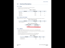
I don't know what installation manual you're looking at (GPS175 or HDX) because 5-2 of the HDX manual refers to something else entirely, and there is no 5-2 in the GPS175 install manual. But in any case, the GPS175 manual, on page 86 and 88, Figures B-1 and B-2 in Appendix B, clearly show that both power pins (21 and 42) and both ground pins (20 and 41) are jumpered together outside of the unit. And this was the way my wiring harness was built....I think that the pin diagram on page 5-2 of the installation manual shows pins 21 and 42 to be jumpered internally. So, my question is, can I connect power to either pin 21 or pin 42, or do I have to connect power to both? If I am reading the diagram correctly, I think I can use either one but don't need to use both. Same question regarding ground to pins 20 and 41.
If you need a copy of the GPS175 Installation manual, I have Revision 2 from March, 2019. I'm sure they haven't changed the pinouts since then, if there's been a revision of the manual. Get in touch via email if you're interested.
Speeddog8
Member
- Joined
- Mar 30, 2010
- Messages
- 66
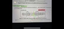
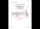
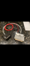
This should be all that you need. Also, please note that as regard the tiny little config module wiring, the yellow wire is ”Data” and the white wire is “Clock”. I had to ask Stein for this info as I could not locate it in the Garmin install manual for the GPS175. I highlighted below all of the pins on the GPS175 that have connections in my install with ARINC 429, power, ground, etc. I hope this helps.
Attachments
-
 2016A8BF-0ABA-40E9-BF4E-A16CE40B82D2.png746.7 KB · Views: 541
 -
 F67EFDD1-4480-45DE-8BD4-3FE69049C581.png4.5 MB · Views: 710
 -
 584D2BAA-626E-4A00-8357-229D0B842015.png1.1 MB · Views: 664
 -
 0D580796-2686-440D-9B07-B055CFABB205.png2.3 MB · Views: 519
 -
 373806A2-709F-43E3-8E41-2C4E4C4EF309.png2.9 MB · Views: 492
Rhino
Well-Known Member
- Joined
- Jul 20, 2009
- Messages
- 1,871
Coupled with what Marc said, that almost makes sense. The aircraft wiring should be capable of handling far more current than the box can use, but circuit board traces could be another story. Circuit board traces can be designed to carry what's necessary, but changes or unanticipated consequences do sometimes prove more than an original design can handle. My guess is they made a change to the unit that required more internal current, but the original board wasn't designed to handle it. So instead of designing an entirely new circuit board and starting all over from scratch, they just patched additional power into another point on the board by tying in another pin. That's just a guess of course, but it does sort of fit.... I think the answer was current carrying ability, not of the wires or connector but of whatever is inside the box (circuit board traces or something I guess)...
Last edited:
John Bright
Member
I see folks in this thread are referencing two different Garmin installation manuals... 190-02207-A1 rev2 (AML STC) and 190-02207-00 rev2 (TSO). I have both if you send me a message on this forum.
A bottom line about the two power pins is that both IMs say "All power leads and ground leads are required." Ref 190-02207-A1 rev2 page 88, note 3 and 190-02207-00 rev2 page 11-3, note 1.
It's common practice across manufacturers to use multiple power pins.

 is that both IMs say "All power leads and ground leads are required." Ref 190-02207-A1 rev2 page 88, note 3 and 190-02207-00 rev2 page 11-3, note 1.
A bottom line about the two power pins is that both IMs say "All power leads and ground leads are required." Ref 190-02207-A1 rev2 page 88, note 3 and 190-02207-00 rev2 page 11-3, note 1.
It's common practice across manufacturers to use multiple power pins.
- I've always thought the use of multiple power pins was due to pin current capacity but GPS 175 max current at 14V is only 0.9A. Maybe there are a couple reasons, redundancy and current capacity.
- Bob Nuckolls teaches us to use lengths of wire as ballast resistors to balance the load through D-Sub pins. Here he speaks to Size 20 pins (0.040" diameter) with 22 awg wire. The GPS 175 62-pin connector uses Size 22D pins (0.030" diameter). The GPS 175 manual does not show such ballast resistor wire lengths.
- Unfortunately, multiple power pins can lead some installers to believe the pins are diode or'd which is some cases they are. I suspect in general if the pins are physically adjacent they are not diode or'd but one always needs to find this explicitly stated in the installation manual. The pins in the GPS 175 are clearly not diode or'd since they are shown connected in parallel external to the connector.
Thanks everyone for your help. One of the reasons i had asked was that one power pin bent and shorted to the shell. It was very hard getting out and the hole was damaged, and I wondered if I could just abandon that pin. I also sent the question in to Garmin and their answer was consistent with everyone's response on this forum. I just cut off the old connector and remade the connectiions using a new connector, using both power pins and both ground pins. All is good now.
cjohngraham
I love flying!
- Joined
- Aug 5, 2016
- Messages
- 26
Could you send the TSO version of the IM? I have the AML. jgbehu@gmail.com. thanksI see folks in this thread are referencing two different Garmin installation manuals... 190-02207-A1 rev2 (AML STC) and 190-02207-00 rev2 (TSO). I have both if you send me a message on this forum.
A bottom line about the two power pins is that both IMs say "All power leads and ground leads are required." Ref 190-02207-A1 rev2 page 88, note 3 and 190-02207-00 rev2 page 11-3, note 1.
It's common practice across manufacturers to use multiple power pins.
- I've always thought the use of multiple power pins was due to pin current capacity but GPS 175 max current at 14V is only 0.9A. Maybe there are a couple reasons, redundancy and current capacity.
- Bob Nuckolls teaches us to use lengths of wire as ballast resistors to balance the load through D-Sub pins. Here he speaks to Size 20 pins (0.040" diameter) with 22 awg wire. The GPS 175 62-pin connector uses Size 22D pins (0.030" diameter). The GPS 175 manual does not show such ballast resistor wire lengths.
- Unfortunately, multiple power pins can lead some installers to believe the pins are diode or'd which is some cases they are. I suspect in general if the pins are physically adjacent they are not diode or'd but one always needs to find this explicitly stated in the installation manual. The pins in the GPS 175 are clearly not diode or'd since they are shown connected in parallel external to the connector.
View attachment 5307View attachment 5309 is that both IMs say "All power leads and ground leads are required." Ref 190-02207-A1 rev2 page 88, note 3 and 190-02207-00 rev2 page 11-3, note 1.