Heated Pitot In Carbon Fiber Wing

mrdaud

Member
Joined
Sep 28, 2009
Messages
122
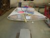
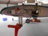
There are a number of ways to to do it, but it would be the same as any fiberglass composite wing.  I placed my PT at the wing tip as far out as possible.  As the wing structure is not flat in the forward position of the wing, I built up a pad of structural aerosil (resin and fused silica) so it had a flat base and was level for a normal cruise attitude, and as far forward as possible.  I use a PT mast that is inserted from the inside of the wing end, and then attached with screws through the bottom of the wing.  Using the mast makes it an easier install and helps alleviate any airflow disturbance issues around the wing.  Again, this is one of probably several ways, but hope this helps.
 

Attachments

  • P1010013.JPG
    P1010013.JPG
    355.7 KB · Views: 200
  • DSC.jpg
    DSC.jpg
    358 KB · Views: 211

jnmeade

Active Member
Joined
Oct 9, 2011
Messages
330
Location
Eastern Iowa
Thanks, Interesting and useful.
I have a Flight Design CTSW and am working with a wing already built. I have access through one hole. I have to build up a mount so am wondering how to embed the captured nuts. Just "glass them in"? Put them on some kind of frame and glass the frame in? I'm thinking out loud but appreciate the suggestions.
Mine is a heated pitot tube.
 

mrdaud

Member
Joined
Sep 28, 2009
Messages
122
What Ray said. If you look at my first photo, the mount for the
PT controller is done just that way, except I used fiberglass flat stock instead of aluminum. However, I have aluminum plates with nut plates imbedded all over my plane.
 

jnmeade

Active Member
Joined
Oct 9, 2011
Messages
330
Location
Eastern Iowa
I was initially worried about the galvanic action between aluminum and carbon fiber, but apparently there are work-arounds that obviate that concern.
http://eaaforums.org/showthread.php?4503-Carbon-Fiber-Panels-Touching-Aluminum-Frame/page2&s=c701021da8a222e4639e6138ef8c66cd
https://www.corrosionpedia.com/galvanic-corrosion-of-metals-connected-to-carbon-fiber-reinforced-polymers/2/1556
I think I'll fabricate a mount using a carbon fiber sheet, put fasteners on it and then epoxy that to the inside of the wing. May do something similar for the pitot tube mount.
Thanks again.
 

jnmeade

Active Member
Joined
Oct 9, 2011
Messages
330
Location
Eastern Iowa
New development - I am having trouble getting access for the hoses and wires to the pitot tube site I prefer.  One possible option will place the heated pitot tube, mounting apparatus and control very close to the remote magnetometer.

My question is what is the closest I can place those two systems to each other without expecting trouble?  Are there any techniques or procedures that will diminish conflict that is due to proximity?

I've looked at the manual and can't find a stand-off spec.

The power wires for the heated pitot tube controller would be immediately adjacent to the wires to the magnetometer for about 12 feed.
 

dynonsupport

Dynon Technical Support
Staff member
Joined
Mar 23, 2005
Messages
13,226
The heated pitot draws 10A. We'd like to see this at least 30" away from the magnetometer for any wire involved with the heated pitot. There's interference from wires being near one another, it's all about the distance from the actual sensor inside the box.

There is no shielding you can do to reduce interference.
 

jnmeade

Active Member
Joined
Oct 9, 2011
Messages
330
Location
Eastern Iowa
I'm either going to have to do without the remote magnetometer, move it to the fuselage, or cut a hole in the carbon fiber wing to install the heated pitot tube and wiring in the other wing. None of these options is palatable.
 

jnmeade

Active Member
Joined
Oct 9, 2011
Messages
330
Location
Eastern Iowa
I've tentatively decided to move the remote magnetometer from the left wing to the tail in the area covered by the ventral fin. I'll have to take the fin off, fabricate a mount, epoxy it on to the outside of the tail and put the fin back on. Running the wire is no problem. This is a magnetically benign area within the area approved by Dynon for the magnetometer.
Then, I can use the present tube or loom in the wing that the magnetometer wires are currently going through to run the pitot and AOA tubes and heat controller wires.
 

jnmeade

Active Member
Joined
Oct 9, 2011
Messages
330
Location
Eastern Iowa
If I put the heated pitot tube and control box in the left wing and move the remote magnetometer to the tail, can I leave the OAT sensor in the left wing where it is now? I'll run the wires for both the OAT and the heated pitot tube in the same chase.
 

n456ts

Do not write below this line
Joined
Jan 24, 2015
Messages
161
Are you adding an additional alternator to your Rotax? I'm curious where you're going to find those extra 10 amps for the heated pitot.
 

jnmeade

Active Member
Joined
Oct 9, 2011
Messages
330
Location
Eastern Iowa
Yes, I put together the 40A alternator from parts, identical to but not purchased from Rotax. Shipping now. I'm also running a 10W amateur radio.
 

camahl

I love flying!
Joined
Jan 20, 2019
Messages
1
Hi, following on from the comment above about current draw, I'm trying to put together a load analysis for my rotax powered aircraft and I am interested to find out what the typical current draw is for the dynon heated pitot. I understand that the maximum is 10A, but it would be good to get an idea of what it draws under different conditions.

Is there any data for average current draw at different ambient conditions? Or any empirical experience from users?
 

Raymo

I love aviation!
Joined
Apr 25, 2016
Messages
1,066
Location
Richmond Hill, GA
That data would be difficult to ascertain during flight due to other loads on the system and varying temperatures, which would result in different current draws. I believe it would pull up to 10 amps until warm enough, then will pulse on and off to maintain the temperature.
 
Top