TRANSPONDER STILL WEIRD!

MileHighCTLS

New Member
Joined
Mar 6, 2008
Messages
7
Location
Denver
BACKGROUND: Twin Skyview installation with Dynon transponder on a Flight Design CTLS.

I posted before ... thought I had it solved ... but last night ... more problems.

I started with my Transponder getting its two-year IFR certification. Suddenly, a few weeks after that, towers kept telling me my transponder is weak or intermittent. This went on for months. Some days it worked flawlessly, other days not. By the way, whenever controllers say transponder is not working, the Skyview would show a green "transponder on"(no X). However, on the map display, it would say "No TIS" (trafic).

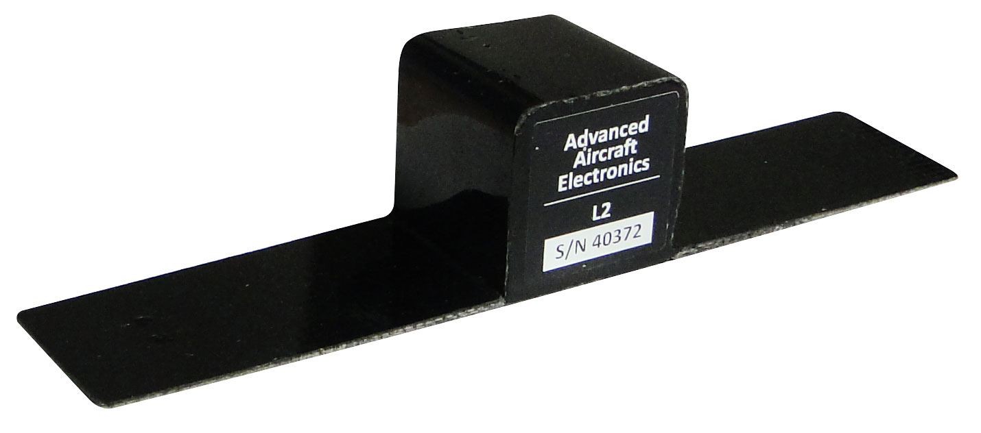
Mind you, everything checked out for certification (in my hangar). And I checked all connections. So, in an effort to fix it, I installed a very large ground plane (see photo). After that everything worked for more than a month! Then, once again, the screen showed "No TIS" and controllers told me my transponder was intermittent!

I am going crazy! Any ideas? Has this ever happened to anyone else? And why does it show "No TIS" whenever transponder is not working, yet the transponder shows "On and working" on the main PDF?
GroundPlain.jpeg
 

jakej

Well-Known Member
Joined
Oct 10, 2007
Messages
2,079
Location
Adelaide, Australia
It's possible that it is a connection that's at fault here if the last thing you did was just add the ground plane - Check the pin in the BNC fitting, make sure it is nearly flush with the body at the opening - in other words not retracted preventing a solid contact.
Also check the fitting in the antenna, it is a piece of round metal tube of a smaller diameter than the BNC 'pin' that is split into 4 segments - check that none of the segments are missing.
I know of a guy who had similar issues - the LAME (A&P) bench checked the Txpndr, tested again in the aircraft, replaced all the coax & connectors & charged a lot of money - I had a look & happened to notice 2 of the metal tube segments in the antenna missing, replaced antenna & problem solved. Not saying this is your issue but it doesn't cost anything to check.
 

XPRSAV8R

Member
Joined
Jul 9, 2019
Messages
80
Location
Houston Area
I had a similar problem. It turned out to be the antenna; it had cracked at the root and was unnoticed. Replacing the antenna solved my problem. Best of luck.
 

JTD

Member
Joined
Oct 26, 2008
Messages
125
Location
dallas tx
I assume by you picture that this is a composite airplane. The ground plane shown that is rectangular will cause the radiation pattern to be incorrect. It needs to be round or a clipped corner circle so it’s radiation pattern will be equal in all directions.

The exact measurements for the ground plane can be found in Jim Whers Antenna
Manual for composite aircraft. The ground plane should be bonded to the coax ground

3557
 

JTD

Member
Joined
Oct 26, 2008
Messages
125
Location
dallas tx
From Jim Weir ( RST) engineering manual:
The MOST IMPORTANT thing to provide the antenna is a good ground plane. This is nothing more than a piece of metal (thickness absolutely not important) cut so that one of the principal dimensions is 51⁄2” and with a 3/8" hole in the center to mount the antenna rod and connector. If you are making it a circular groundplane, then the diameter should be 51⁄2”. If you are making a rectangular groundplane, then each side should be about 41⁄2” long so that the 51⁄2” dimension is in between the 41⁄2” sides and the 61⁄2” hypotenuse of the square. If you want to make it octagonal or hexagonal or pentagonal or any shape you want, have at it. Just remember that it should be roughly symmetric about the center antenna rod.
This antenna should be mounted so that the antenna rod is vertical to the earth’s surface and with the tip of the rod pointing down at the earth. It is certainly permissible to bolt or solder small tabs on the ground plane to attach it to the airplane’s structure, and it is also permissible to drill small holes in the ground plane for the same reason.
If you have a large expanse of metal in the airplane, will this work for a ground plane? Yes, most certainly. If it is many times the 51⁄2” dimension then you rapidly get to the point of diminishing returns. What you want to avoid is a ground plane TWICE or FOUR times the 51⁄2” dimension, as you now have a halfwave groundplane that isn’t any good at all. In short, if it isn’t 51⁄2” then it should be at least 16.5” in all dimensions.
 

MileHighCTLS

New Member
Joined
Mar 6, 2008
Messages
7
Location
Denver
T
I assume by you picture that this is a composite airplane. The ground plane shown that is rectangular will cause the radiation pattern to be incorrect. It needs to be round or a clipped corner circle so it’s radiation pattern will be equal in all directions.

The exact measurements for the ground plane can be found in Jim Whers Antenna
Manual for composite aircraft. The ground plane should be bonded to the coax ground

View attachment 3557
[/QUOTE

Thanks, It came from the factory with an even smaller one, rectangle. I enlarged it. What you say makes sense, but I have heard so many differing opinions about ground planes. The consensus being that any large reflecting surface will do. Because on a metal plane, shape is no issue. I am not disputing what you are saying, merely pointing out the diversity of opinions. It is quite frustrating!
 

JTD

Member
Joined
Oct 26, 2008
Messages
125
Location
dallas tx
Xenon,
Don’t take my word for it. Go to the RST website. Jim Weir wrote the book on composite antennas starting with the Rutan vari EZ. People often look at metal airplanes and assume a big ground plane is beneficial. Note how he discuses staying away from multiples of the 5 1/2 inch and rectangles unless you get very big. 1/2 and 1/4 wave antennas need to have a specific size ground plane. A rectangle creates dead spots in the radiation pattern
 

jakej

Well-Known Member
Joined
Oct 10, 2007
Messages
2,079
Location
Adelaide, Australia
Hey guys, lets get back to the real question, not how much you do or don't know about antennas etc - I'd suggest if you don't have anything useful to add re troubleshooting the original posters problem, then start another topic. He needs focus, not antenna design theory ;) .
 

XPRSAV8R

Member
Joined
Jul 9, 2019
Messages
80
Location
Houston Area
I'll second that, Ray.

Forgot until Ray reminded me. I kept having ATC tell me that they weren't receiving mode C. I replaced my ball tip antenna outside because it was actually broken at the root (couldn't tell from visually). However, I decided to install the L2 antenna that Ray referenced above for my transponder and repurposed my ball tip antenna for ADS-B. Have to admit: I couldn't be happier with performance in my composite plane. ADS-B out performance reports check in every month! Mine is installed in the tail section because there's a warning about strong radio radiation.
 

MileHighCTLS

New Member
Joined
Mar 6, 2008
Messages
7
Location
Denver

MileHighCTLS

New Member
Joined
Mar 6, 2008
Messages
7
Location
Denver
I assume by you picture that this is a composite airplane. The ground plane shown that is rectangular will cause the radiation pattern to be incorrect. It needs to be round or a clipped corner circle so it’s radiation pattern will be equal in all directions.

The exact measurements for the ground plane can be found in Jim Whers Antenna
Manual for composite aircraft. The ground plane should be bonded to the coax ground

View attachment 3557
Quick followup question ... when you say
"the ground plane should be bonded to the coax ground", do you mean simply grounding the antenna on it, which in effect, would connect the coax ground?
 

GalinHdz

Active Member
Joined
Mar 3, 2008
Messages
716
Location
KSGJ/TJBQ
Sound to me that you have an intermittent cable/antenna connection problem caused by normal airplane vibrations. Check or replace the cable and the connectors. I had the same problem so I replaced my cable/connectors with high grade professionally made RG400 cable. The problem went away. After you get consistent operation, you might consider changing the ground plane to a more "rounded" version like JTD posted and not the perfect square you currently have. But fix the intermittent problem first.

Quick followup question ... when you say
"the ground plane should be bonded to the coax ground", do you mean simply grounding the antenna on it, which in effect, would connect the coax ground?
Do NOT bond the coax ground to the ground plane. This will isolate the antenna and the coax, a bad idea. Bond the ground plane to the airframe and make sure your antenna/coax has a good, actually a GREAT, ground connection to the ground plane. Too many times this is where intermittent problems happen, mainly when dirt/corrosion gets between the ground plane and the antenna.
 

JTD

Member
Joined
Oct 26, 2008
Messages
125
Location
dallas tx
On a composite airframe the only way the ground plane becomes the counter pose to the antenna element is by the coax shielding which is swaged under the BNC connector feral. This in-turn grounds the base of the antenna when connected to the antenna connector. With the type of transponder antenna ( high speed) you are using, the two antenna mounting studs are what provide the ground connection between antenna and ground plane. It is important that no composite material be sandwiched between studs , nuts and ground plane, as it will interfere with the bonding. You can drill a few mounting holes in ground plane to attach the antenna / ground plane assembly to the airframe. It not a bad idea to change the coax if you suspect it bad, but you still will have a improper radiation pattern with your rectangular ground plane which will result in intermittent operation.
 
Top