VPX Data to D37 harnass

JurgenRoeland

New Member
Joined
Oct 12, 2023
Messages
16
(updated after response1)
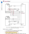
Hi, I have a small question on the connection of the VPX serial data connection to the D37 harnass.
I'm not very confident with wiring yet and feeling better safe than sorry and asking upfront to this wise community.

I read in the VPX manual that you can pick any serial pair and connect the VPX J1-21 Serial GND to any GND pin on the Dynon Skyview D37 between Pin 21 - 24.

I bought 3 conductor shielded wire and was picturing to use solder sleeve to bring J1-21 GND with shield together on the side of the D37, resulting in 1 GND wire arriving from the VPX J1-21.
this 1 GND wire would be connected to Pin 22 GND on D37

My question is, can I just use solder sleeve to to connect the vpx serial gnd + shield to Pin 22 of D37
I tried to make the question as clear as I can in the attached image

A related question is : on D37, are pin21, 22, 23, 24 GND pins internally all connected to the same GND line ?
(in other words, if connecting only the VPX J1-21 serial GND with shield in my image to IN on pin 23 and not link that further linto GND bus, does that loop through the main GND bus via pin 21 and 22 which go direct to GND bus ?

many thanks in advance.
 

Attachments

  • Capture2.JPG
    Capture2.JPG
    95 KB · Views: 87
  • Capture.JPG
    Capture.JPG
    70.7 KB · Views: 83
Last edited:

maartenversteeg

I love flying!
Joined
Oct 26, 2011
Messages
212
For the 37-pin connector both pins 1 and 2 go to the fuse of the 12V supply and both the pins 21 and 22 are connected to avionics ground, this takes care of the power supply to the Dynon display. You can connected the ground of the serial interface.
Connecting the shield to the ground either add this to pin 21 or 22 provides a clean shielding of the serial connection. I assume that the device on the other side has it's own grounding connection to the avionics ground. So if you connect the shield of the serial cable also to the device you will create a ground loop. Whether it is better the keep the shielding on the device side unconnected and prevent the ground loop or connect it and create a ground loop but have an additional path is a debatable issue and left to the preferences of the installer both will most likely work as rs-232 interfaces are not too sensitive to noise It is more important in the audio connections wiring and grounding
 

JurgenRoeland

New Member
Joined
Oct 12, 2023
Messages
16
sorry I got confused, I meant pin 23, another free Black GND on D37, (travelling and not close to the plane now and remember that I indeed connected 21 and 22 to GND bus and 1 and 20 to the main power of vpx J12-9.

so please let me rephrase it as pin 23, I'll update the main question above as well

if I understood the rest of your explanation wel on the ground loop issue, then it sounds like it's better to not connect the D37 side to the VPX serial GND line?
 

maartenversteeg

I love flying!
Joined
Oct 26, 2011
Messages
212
In the wiring example you see the different variants in the connection. If a ground is added as the thrid wire in the bundle then you can connect it either to 21 or 22. 23 can also be used as it it a direct ground connection on the Dynon Display, but is has a default assignment as backup battery ground, so when you use the standard cable that is provided with the Dynon display that pin is already wired to the backup battery connector. I you don't use a backup battery and are sure you don't want to add a backup battery to yous system then you could cut off that connector and uase pind 23 but the ground, or 24 whatever you like.
You might want to consider leaving the backup battery connector in place in the bundle, as you might in the future realize that with you personal way of operating your system you want to be able to have the Dynon running during engine start and at that point the backup battery will keep the Dynon display alive. But as said those are personal decisions that you are allowed to make for your plane.
 

JurgenRoeland

New Member
Joined
Oct 12, 2023
Messages
16
I did buy the backup battery so J23 is not a good option then. J24 goes on GND of the the gps so that leaves 21 and 22 if I would follow the recommendations in the VPX manual.

Did I understand your first answer on ground loop well that it's probably better to solder the vpx J1-21 gnd line together with the shield of the 3 conducter wire near the end of D37 but not connect it anywhere on D37 ? VPX is indeed also GND via a pin to the firewall main GND block
 
Last edited:

maartenversteeg

I love flying!
Joined
Oct 26, 2011
Messages
212
Yes, and in this kind of setup you would want to connect the shield on one side to ground, a not-connected shield (electrically floating), does not provide the shielding that you are trying to achieve by using shielded cables. So in this setup using a 3-conductor cable with shielding is the 'best' way to go. If you only had a 2-wire shielded cable then you might have considered connecting the shield on both sides, but the 3-wire shielded cable is the most clean option.
 
Top