

Rhino
Well-Known Member
- Joined
- Jul 20, 2009
- Messages
- 1,915
He asked for a simple explanation and this got really complicated in some ways. The shunt itself does not reduce anything, but wiring it in parallel with the EMS does reduce the amount of current through the EMS. So I think this is just a matter of different terminology.
I'll adapt something I posted elsewhere about using potentiometers in parallel, and hopefully that will help clear things up somewhat.
Consider these circuit diagrams. These diagrams use 12 volts, which may not be what you'll consistently have on the ammeter line, but I'm just using 12 volts to demonstrate the concept. We'll start with this diagram of two series circuits.
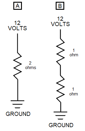
Someone already mentioned Ohm's law of E = I x R, where E is voltage, I is current, and R is resistance. That translates to Voltage = Current x Resistance. Because E = I x R, the total current in these circuits must be 6 amps (12 = 6 x 2).
Both circuits A and B are a single series leg, or path, and have 12 volts at the top and ground at the bottom, so they will all drop a total of twelve volts. That cannot change, because any leg between ground and a supplied voltage must drop the entire voltage across the entire leg. Different resistance values within each leg will drop different amounts of voltage individually, depending on those resistance values, but the entire leg still drops the entire voltage. The total resistance of both circuits is 2 ohms, but the single resistor in circuit A drops the entire 12 volts, while each resistor in circuit B drops 6 volts, for a total of 12 volts. If you put a voltmeter between the two resistors in the right leg, you'd measure 6 volts. Because both circuits A and B only have one leg, they will also both drop the entire current load of 6 amps across that one leg. In series, a single leg drops the entire voltage and entire current levels. However, that changes when you start dealing with parallel circuits.
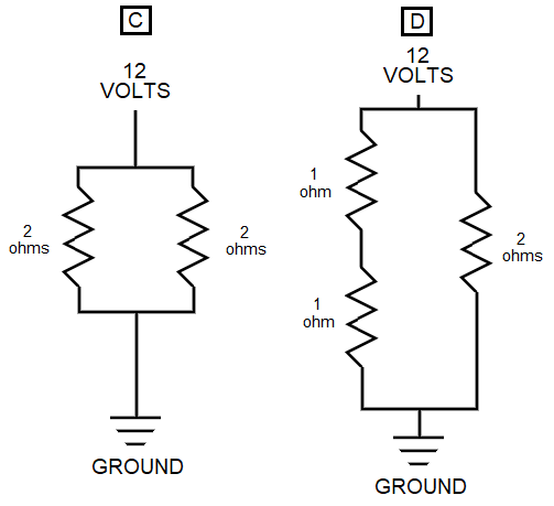
Circuits C and D are parallel circuits. Each leg has the same resistance as the single leg in circuits A or B. Each of the parallel legs will still drop the entire 12 volts, because, as I said before, any leg between ground and a supplied voltage must drop the entire voltage. But, while the entire voltage is dropped on each parallel leg, the current divides between them. If both legs have the same resistance, as shown in circuits C and D, each leg will drop half the 6 amp total current of the circuit, or 3 amps each. The entire circuits will still carry the full 6 amps of current, because current in each leg adds up instead of staying the same, like voltage does.
However, if you start changing resistance values between the legs, the amount of current they carry will change as well.
Now let's modify circuit C into a new circuit E. We'll pretend we have an EMS circuit on the right leg instead of a simple resistor, but it would still have a resistance value. However, we'll assume this EMS circuit isn't capable of handling 3 amps, so we have to change the resistance values to make the leg on the left carry more current. I should note that resistors are called resistors because they resist current flow. A higher value of resistance will result in less current going through.
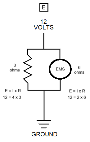
The entire circuit would still maintain the same 6 amp current level. But now, because the leg on the right with the EMS on it has higher resistance, it will have only 2 amps of current vs the 4 amps on the left leg. That is basically the same function the shunt serves. It has less resistance, so it can handle more current, leaving the more sensitive EMS circuit to carry less current.
Because of Ohm's law, any change in current will produce a corresponding change in voltage on both legs. That will change the voltage seen at the EMS, and the EMS is calibrated to interpret the voltage change to determine the current level.
Obviously our aircraft circuits will have many more components in play, and varying voltage levels, but this (hopefully) will help some of the folks with less electronics knowledge at least understand the basic principles involved.
PS: Math has never really been my forte, so somebody please let me know if I got any numbers wrong.
I'll adapt something I posted elsewhere about using potentiometers in parallel, and hopefully that will help clear things up somewhat.
Consider these circuit diagrams. These diagrams use 12 volts, which may not be what you'll consistently have on the ammeter line, but I'm just using 12 volts to demonstrate the concept. We'll start with this diagram of two series circuits.
Someone already mentioned Ohm's law of E = I x R, where E is voltage, I is current, and R is resistance. That translates to Voltage = Current x Resistance. Because E = I x R, the total current in these circuits must be 6 amps (12 = 6 x 2).
Both circuits A and B are a single series leg, or path, and have 12 volts at the top and ground at the bottom, so they will all drop a total of twelve volts. That cannot change, because any leg between ground and a supplied voltage must drop the entire voltage across the entire leg. Different resistance values within each leg will drop different amounts of voltage individually, depending on those resistance values, but the entire leg still drops the entire voltage. The total resistance of both circuits is 2 ohms, but the single resistor in circuit A drops the entire 12 volts, while each resistor in circuit B drops 6 volts, for a total of 12 volts. If you put a voltmeter between the two resistors in the right leg, you'd measure 6 volts. Because both circuits A and B only have one leg, they will also both drop the entire current load of 6 amps across that one leg. In series, a single leg drops the entire voltage and entire current levels. However, that changes when you start dealing with parallel circuits.
Circuits C and D are parallel circuits. Each leg has the same resistance as the single leg in circuits A or B. Each of the parallel legs will still drop the entire 12 volts, because, as I said before, any leg between ground and a supplied voltage must drop the entire voltage. But, while the entire voltage is dropped on each parallel leg, the current divides between them. If both legs have the same resistance, as shown in circuits C and D, each leg will drop half the 6 amp total current of the circuit, or 3 amps each. The entire circuits will still carry the full 6 amps of current, because current in each leg adds up instead of staying the same, like voltage does.
However, if you start changing resistance values between the legs, the amount of current they carry will change as well.
Now let's modify circuit C into a new circuit E. We'll pretend we have an EMS circuit on the right leg instead of a simple resistor, but it would still have a resistance value. However, we'll assume this EMS circuit isn't capable of handling 3 amps, so we have to change the resistance values to make the leg on the left carry more current. I should note that resistors are called resistors because they resist current flow. A higher value of resistance will result in less current going through.
The entire circuit would still maintain the same 6 amp current level. But now, because the leg on the right with the EMS on it has higher resistance, it will have only 2 amps of current vs the 4 amps on the left leg. That is basically the same function the shunt serves. It has less resistance, so it can handle more current, leaving the more sensitive EMS circuit to carry less current.
Because of Ohm's law, any change in current will produce a corresponding change in voltage on both legs. That will change the voltage seen at the EMS, and the EMS is calibrated to interpret the voltage change to determine the current level.
Obviously our aircraft circuits will have many more components in play, and varying voltage levels, but this (hopefully) will help some of the folks with less electronics knowledge at least understand the basic principles involved.
PS: Math has never really been my forte, so somebody please let me know if I got any numbers wrong.
Attachments


Last edited: