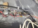
What does the Shunt do?

Steve SR

Member
Joined
May 19, 2020
Messages
38
Trying to understand my electrical system better (I had it professionally done and helped), but can someone in simple airline pilot/dummy language explain what the Shunt in the Skyview HDX system does and is for?

I know it's not a fuse or a CB, we've got it wired Low off the + master solenoid and High from the Alternator CB Load (Rotax external alternator), starter is not in the sequence.

TIA
 
Last edited:

Rhino

Well-Known Member
Joined
Jul 20, 2009
Messages
1,896
Your aircraft produces much more current than your EMS can handle, and it would very likely fail if you put all that current through it. The shunt is wired in parallel, so it takes most of the current, and the EMS only receives a smaller amount.
 

maartenversteeg

I love flying!
Joined
Oct 26, 2011
Messages
246
Its the basic electricity that you can never measure either current or voltage completely separate, you always need a small current to measure voltage and you need some voltage to measure current. The simplest story is that the relative large current (number of amps) flows through the small shunt resistance (say 60 mOhm) and that flowing current created a small voltage drop over the shunt. Then the EMS (pins 24/25) measure that voltage created by the shunt resistance. 60 mOhm and a current of say 8 Amp creates a voltage drop of 480 mVolt (Ohms law) over the shunt and that voltage can be measured by the EMS. The EMS input is a relatively high impedance input and only such a small part of the current flowing through the shunt going into the EMS, that this can be neglected, the EMS mostly measures the voltage over the shunt.
 

cbretana

Active Member
Joined
Jul 10, 2019
Messages
312
It's analogous to measuring flow in a pipe by measuring the drop in pressure from one point in the pipe to another that is a fixed, known distance downstream from the first point. As the flow increases (imagine a valve on the output of the pipe), the pressure drop across a fixed segment of the pipe will increase, in a linear fashion.
 
Last edited:

cbretana

Active Member
Joined
Jul 10, 2019
Messages
312
Yes, this is not just an Analogy. It is exactly what Voltage and Current are. Current is the number of electrons that move through the wire per unit of time, and voltage is the force that is pushing them. Ohms's law makes that clear. Current = Voltage [V] / Resistance[R], or V= IR
 

Steve SR

Member
Joined
May 19, 2020
Messages
38
Thanks everyone, I'm getting it now.

30 years ago I missed 22 out of 25 questions on my first airline ground school open book take home exam on the electrical system, it's always been a weak spot for me and I find that if I go back to crawl-walk-run on things I don't understand I learn it faster.
 

PhilzSkyHdx

Member
Joined
Oct 11, 2025
Messages
35
Thanks everyone, I'm getting it now.

30 years ago I missed 22 out of 25 questions on my first airline ground school open book take home exam on the electrical system, it's always been a weak spot for me and I find that if I go back to crawl-walk-run on things I don't understand I learn it faster.

Find yourself a Basic Electricity course and all this should become quite obvious.

here's a more detailed explanation:
(Warning: this is AI generated so check the installation manual for accuracy)
To indicate 13.6 volts on a general-purpose pin (GP input) of the Dynon SV-EMS-220, the sense voltage applied to the pin must be scaled down using a voltage divider to roughly 1.78 volts. Dynon’s general-purpose inputs are designed for a maximum of 5V, so they require an external resistor to safely measure higher voltages.

How to calculate and wire:
The Math: Dynon uses a piecewise linear calibration where the pin measures a fraction of the total voltage. For 13.6V, you are dropping it to a nominal value between 1.5V and 2V.

The Setup: Connect a 10 kΩ resistor in series with the positive voltage source to the pin to step it down.

Calibration: In the SkyView HDX setup menu (SETUP MENU > HARDWARE CALIBRATION > EMS CALIBRATION), you map the raw voltage input of the pin to read exact Volts (e.g., 13.6 V) by adding calibration points.
 
Last edited:

Marc_J._Zeitlin

Active Member
Joined
Sep 24, 2007
Messages
356
Location
Tehachapi, CA 93561
here's a more detailed explanation:
(Warning: this is AI generated so check the installation manual for accuracy)
More detailed, sure. Accurate, no.

Page 7-44 of revision AT of the Skyview HDX installation manual very clearly indicates that all you have to do to measure VOLTAGE at one or two locations in your electrical system (I use the cold side of the master solenoids for my two buses) is hook up pins 1 and 2 on the D37 connector to those sources and call it good. No resistors, no calibration, nada. The system understands that it's measuring voltage on those pins.

All the AI stuff above is, to put it bluntly, innacurate and not useful. If you want to use OTHER D37 pins than Dynon says should be used for measuring voltage, sure - maybe some of that will apply, but a review of the installation manual will say for sure, and merely telling folks that they should vet what you're posting is inappropriate - don't post it if you haven't vetted it yourself.

This is just another data point indicating that using AI without vetting the output with the original source is GIGO. No one should be posting AI output without ensuring that they've vetted it for accuracy.

And with respect to the shunt and measuring current flow, @huntaero nailed it simply and accurately.
 

PaulSS

I love flying!
Joined
Feb 21, 2019
Messages
123
Screenshot 2026-07-19 at 09.59.24.png
 

greentips

Member
Joined
Nov 26, 2020
Messages
39

Steve SR

Take a good look at the Dynon IM page. It describes how to use the shunt, but not exactly what it does or why it works.

So, fluid systems are often used to describe how electricity works in circuits. They're very different, but they can illustrate fundamental principles without getting lost in the math weeds. (see huntaero's comment). Now the details.

Think about a spigot with two garden hose connections and a well pump that supplies 50 psi. We'll call that voltage for electricity.
Then think about connecting two hoses to that spigot, one 2" in diameter, and one 2 mm in diameter (about 1/4").
Turn on the faucet and open the valve for the 2" hose (50 mm). Water will flow. We'll call that current for electricity.
Take a good picture of a typical garden hose in your yard (or at the airport when you're washing the plane).
You will see lots of water flowing through the open end of the 2" hose but not a huge amount of pressure, unless you put your thumb over the end of the hose. Then you'll feel pressure on your thumb and the water will spray out faster and harder. We'll call your thumb resistance.

That is the fundamental way electricity works: a driving force called voltage, a flow of electrons (or charges in this case negative) called current measured in amperes. Amps are simply a measure of how many charges are flowing in a wire over a fixed time, and that flow is governed by how much resistance is in the wire or circuit components.

Now if you bend your flowing garden hose over, you've created a blockage turning off the flow. Once the pressure in the hose reaches the pressure from the pump it stops flowing. Or you can turn off the valve and get the same thing and the water will stop flowing a few seconds after you turn off the valve, blocking the flow, provided it is strong enough to stop the water.

Now, turn on the valve for the very small hose. What do you get? A powerful stream of water. The small hose offers a major difference in resistance to flow compared to the big hose.

So it is with a shunt. There is a big wire (that flat metal plate between the binding posts) which nearly all of the current flows powering the ship's electrical system or whatever is downstream of it as the Dynon diagram shows. Very low resistance, large current flow, little voltage (pressure) drop.

But the "shunt" portion is the very small hose, very high resistance, small current flow.

So, when you open both valves on the spigot and let water flow through both hoses at the same time, which one will carry more water (current)?
The big one, of course, which is why we use big hoses to carry a lot of water. But the trickle of water coming out of the small hose is still useful for figuring out the flow through the large hose. Same amount of water passing through both hoses, but vastly different flow rates.

The voltage difference (pressure difference) across a high resistance will be smaller for the same current flowing from the battery, than it will be across the low resistance. (Ohms law combined with Kirchoff's Current Law).

1784465195046.png


This diagram shows the relative currents across the shunt. R1 is the small hose, R2 is the big hose. Current coming in (IT) = current going out.
Current crossing the high resistance (R1) is different from low resistance (R2).

So, this brings the obvious question: Why do we need a shunt at all? Why not just stick a meter in the feed line from the alternator and be done with it?

And the reason is that most aircraft alternators can make about 60 to 140 Amps of current. To meter these circuits directly you need a winding in the meter with wire big enough to handle the full current load. Take a look at the wire coming off the battery. Big heavy meter.

With the shunt we only need to pass a few milliAmps and measure current across that high resistance so the meter can use very fine wire to measure great voltage swings without burning out. All voltmeters work by creating a current flow through a coil which creates a magnetic field and swings the needle. (digital meters have similar principles but different implementations).

Hope this is helpful to the airline pilots out there. Especially those with grandchildren like mine who when he was four, sitting in the right seat gave me the FO roll eyes look that says he's thinking, "Does the captain know what the heck he's doing!? or is he out of his mind????"

He gives me the same look when I tell him we'll talk about Heisenberg's Uncertainty Principle tomorrow.

 

Steve SR

Member
Joined
May 19, 2020
Messages
38
Find yourself a Basic Electricity course and all this should become quite obvious.

Can you recommend one? I've been read and rereading the usual books (AeroElectric Connection by Nuckolls), Aircraft Wiring Guide by Ausman) but obviously I've still got a lot to learn.

Thanks
 

Rhino

Well-Known Member
Joined
Jul 20, 2009
Messages
1,896
Can you recommend one? I've been read and rereading the usual books (AeroElectric Connection by Nuckolls), Aircraft Wiring Guide by Ausman) ....
Those aren't basic electronics courses. It's been many years since I taught electronics in the Air Force, and I confess I haven't really kept up with what's available out there. From casual browsing, there appears to be quite a few good ones, but none are fantastic. Some actually have you build basic circuits, to help understand them. I wouldn't consider that really necessary though.
 

Steve SR

Member
Joined
May 19, 2020
Messages
38

Steve SR

Take a good look at the Dynon IM page. It describes how to use the shunt, but not exactly what it does or why it works.

Hope this is helpful to the airline pilots out there. Especially those with grandchildren like mine who when he was four, sitting in the right seat gave me the FO roll eyes look that says he's thinking, "Does the captain know what the heck he's doing!? or is he out of his mind????"

He gives me the same look when I tell him we'll talk about Heisenberg's Uncertainty Principle tomorrow.

HA! I was a career mainline WB FO, retired with 6,0 in the 77 and a biscuit short of 10,0 in the 78. At the end I was getting career 73 Captains who had never flown international and they'd give me the same look. "You're a FO, what do you know?" Then after SIN ate their lunch after a 17 hour flight....


"how to use the shunt, but not exactly what it does or why it works." EXACTLY!!!!!!! Thanks for taking the time to post all this!
 

Attachments

  • Shunt wiring (1).jpg
    Shunt wiring (1).jpg
    265.3 KB · Views: 10
  • Shunt wiring (2).jpg
    Shunt wiring (2).jpg
    304.2 KB · Views: 9
  • Shunt wiring (3).jpg
    Shunt wiring (3).jpg
    280.9 KB · Views: 9
Last edited:

Steve SR

Member
Joined
May 19, 2020
Messages
38
This is another thing I started last week. I've got all the connections written on a big Word document, and I thought it was silly at the start but it turns out drawing the system and subsystems on a BIG piece of paper makes some things obvious. Like that LINE is on the bottom of my switches, but on the TOP of my CBs.
 

Attachments

  • A big sheet of paper.jpg
    A big sheet of paper.jpg
    398.6 KB · Views: 4

greentips

Member
Joined
Nov 26, 2020
Messages
39
Steve,

As for your best bet to learn basic electricity, there are a couple of resources. An easy one to start with the very basics is a ham radio handbook published by the ARRL. It has a couple of chapters on basic electricity and a very practical approach to circuits. Bonus is if you get really interested you can pass the FCC ham license exams and we can set up a schedule and talk on your next expensive hobby. You could probably find a local ham and ask to take a look at the book, and he'll probably talk about radio forever.

Second most undergrad lower division physics courses will have a semester of electricity and magnatism. Pretty much any text book that is used in second semester physics courses will teach basic circuits and electricity and magnetism theory. Most of them have problems at the end of each chapter with answers and explanations. Old books are every bit as good as the new ones.

If you want a little more formal billing, you could check your local community college and see if they offer an intro physics/electricity and magnetism course. They're usually pretty cheap and well taught, but you're committed to a classroom schedule.

At Michigan we had a thinned out course called "Physics for Poets" aimed at freshmen/sophomores who wanted a little real science to balance out their education that covered pretty much up to the level of basic DC and a little AC circuits. But we did teach real and interesting stuff in a way that non-math/science folks could 'get it.' Something like that might be useful but would likely include more than you're interested in. Except physics is cool. And I'm just an airport geek, these days. But be glad to answer the nitty gritty off line so we don't bore the board.
 
Top